Lighting / Fixtures
Installation Guide for BELL Lighting 08187V2 Firestay LED Downlight
Installation guide for the BELL Lighting 08187V2 Firestay LED Downlight. Includes wiring, cutout dimensions, CCT/wattage settings, and safety instructions.
Table of contents
Manual images
Click an image to enlargeImportant Installation Information
This equipment must be installed by a competent electrician in accordance with current IEE wiring regulations (BS7671:2018) and local building control. The light source of this luminaire is not replaceable; when it reaches the end of its life, the whole luminaire must be replaced. Ensure the ambient room temperature does not exceed 30°C. Always switch off the mains supply before installing.
Technical Specifications
- Cut Out Diameter: 65-70mm
- Insulation: IC Rated (can be covered with insulation material)
- Adjustable Settings: 4 CCT (2700k, 3000k, 4000k, 6000k) and 2 Wattages (5W/7W)
Installation Steps
- Cut a suitable diameter hole in the ceiling (65-70mm), ensuring it does not infringe on electrical cables, water/gas pipes, or ceiling joists.
- Remove the bezel and adjust the required colour temperature and wattage using the switches located under the magnetic bezel.
- Wire the female connector (separate in the package) to the circuit.
- Connect the male connector (attached to the lamp) to the female connector, ensuring they are fully 'clicked' together.
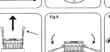
- Fold the spring clips upwards and insert the fitting into the hole.
- Test for correct operation.
Wiring
The wiring terminals are marked as follows:
- L: Live (Brown)
- E: Earth (Yellow/Green)
- N: Neutral (Blue)
- LO: Loop
Maintenance
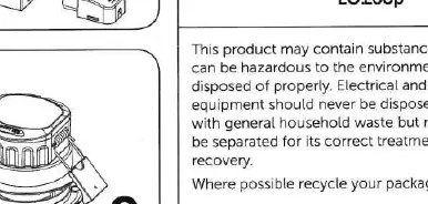
To change the bezel, simply place the magnetic bezel on the fitting. This product contains substances that can be hazardous to the environment if not disposed of properly; it should be separated for correct treatment and recovery.
Manufacturer information
BELL Lighting
Practical help
Common problems
Light not working
Ensure the male and female connectors are fully 'clicked' together and check all wiring connections.
Incorrect CCT or wattage
Remove the magnetic bezel and adjust the switches located underneath to the desired settings.
Before use
- Ensure power is switched off at the mains.
- Verify the ceiling cutout is 65-70mm.
- Confirm the installer is a competent electrician.
- Check that the ambient temperature will not exceed 30°C.
Images and diagrams
- Fig 1: Cutting the hole.
- Fig 2: Adjusting settings.
- Fig 3: Connecting the male and female connectors.
- Fig 4: Inserting the fitting.
- Fig 5: Folding spring clips.
Model compatibility
- Compatible with insulation material (IC Rated).
- Requires competent electrician installation.

Manual page author
Michael Turner
Technical manual editor
Reviews PDF manuals for structure, safety notes, and practical product details so readers can find the right information quickly.