Home / Electrical Accessories
Commercial Electric 1.2-Watt LED Emergency Remote Head
Quick guide for the Commercial Electric 1.2-Watt LED Emergency Remote Head. Includes installation steps, wiring instructions, battery replacement, and troubleshooting tips.
Table of contents
Manual images
Click an image to enlargeQuick guide from the manual
This emergency remote head is designed for indoor use. Before beginning, ensure you have all required tools: Phillips and flat screwdrivers, wire strippers, wire cutters, a ladder, safety glasses, and a power drill with a 3/16-inch drill bit. Always consult with your local fire marshal or code enforcement office regarding municipal color guidelines before installation.
Installation
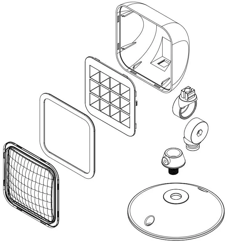
Preparing the emergency head: Set the rubber gasket (EE) into the bracket (G), then insert the bracket into the canopy (H). Secure using the washer (FF) and hex nut (GG).
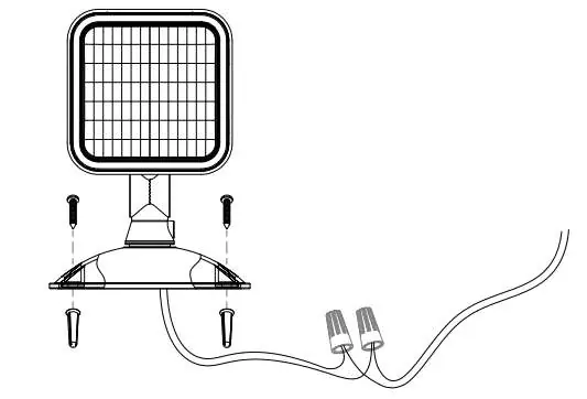
Mounting: Use the provided mounting screws (CC) and wall anchors (BB) to attach the unit to the wall. The maximum mounting height is 9.75 ft (2.97 m).
Wiring: Connect the wires using the provided wire nuts (AA). For 3.6-9.6V applications, connect the brown wire to the positive (+) terminal and the gray wire to the negative (-) terminal.
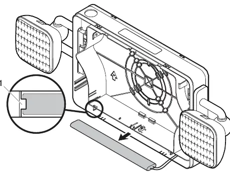
Adjustments: Use Screw 1 to position the head left and right. Use Screw 2 to position the head up and down.
Maintenance and Testing
National Electric Code (NEC) and NFPA life safety code regulations require routine testing. With AC power applied, the EXIT sign and A/C Power LED indicator should illuminate. Pressing the TEST button (I) should turn off the LED indicator, while the EXIT sign remains illuminated and the emergency heads turn on.
Battery Testing: Test the battery once per month. Perform a full 90-minute test every 12 months by disconnecting the main power supply; the unit should remain illuminated for at least 90 minutes.
Battery Replacement
The fixture uses a Ni-Cd Rechargeable AA1000 mAh 9.6 V battery. To replace it:
- Bend the battery catches away from the battery and remove it from the housing.
- Disconnect the battery leads from the board terminal.
- Connect the new battery to the board terminal.
- Place the new battery in the housing and ensure it is seated behind the battery catches.
Troubleshooting
If the LED charge indicator does not illuminate, ensure the AC power supply is on, the unit is wired correctly, and the battery is connected. If the emergency heads do not illuminate, ensure the battery is connected and properly charged. If the battery is discharged, allow the unit to charge for 24 hours before re-testing.
Manufacturer information
Commercial Electric
Practical help
Common problems
LED charge indicator does not illuminate
Ensure AC power is on at the breaker/fuse box, verify correct wiring, and ensure the battery is connected.
Emergency heads do not illuminate
Verify the battery is connected. If the battery is discharged, allow the unit to charge for 24 hours and re-test.
Before use
- Check with local fire marshal for municipal code compliance.
- Ensure all parts from the package contents list are present.
- Turn off electricity at the circuit breaker before starting.
- Verify mounting height does not exceed 9.75 ft (2.97 m).
- Wear safety glasses during installation.
Specs in practice
- Input Voltage
- 3.6-9.6VAC.
- Mounting Height
- Maximum 9.75 ft (2.97 m).
Images and diagrams
- Exploded view shows the assembly order of the rear cover, reflector, silicone pad, lens, rotation brackets, and canopy.
- Wiring diagram illustrates connecting the brown wire to positive (+) and the gray wire to negative (-) using wire nuts.
Model compatibility
- For indoor use only.
- Do not mount near gas or electric heaters.

Manual page author
Michael Turner
Technical manual editor
Reviews PDF manuals for structure, safety notes, and practical product details so readers can find the right information quickly.