Smart Home / Smart Plugs & Strips
Bestten 15A Standard Decor Receptacle Outlet Installation Instructions
Installation guide for Bestten 15A Standard Decor Receptacle Outlets (models LD-3012 and LD-3012TR). Includes wiring diagrams, safety warnings, and technical specifications.
Table of contents
Manual images
Click an image to enlargeQuick Installation Guide
This document provides installation instructions for the Bestten 15A Standard Decor Receptacle Outlet. Before beginning, ensure the power is turned off at the circuit breaker or fuse box. This device is intended for use with copper or copper-clad wire only and must be installed in accordance with local electrical codes.
Installation Steps
- Turn off power to the outlet box at the circuit breaker or fuse box.
- Verify that the power is off before proceeding with any wiring.
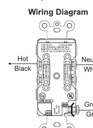
- Connect wires according to the wiring diagram:
- Connect the Black (Hot) wire to the Brass screw.
- Connect the White (Neutral) wire to the Silver screw.
- Connect the Green or Bare (Ground) wire to the Green screw.
- Ensure terminal screws accept #14 or #12 AWG solid copper wire only.
- Tighten every screw to 14 pound-inch (1.6Nm) of torque. Ensure no bare conductors are exposed.
- Mount the device in the wall box using the provided screws and attach the wall plate.
- Restore power at the circuit breaker or fuse box.
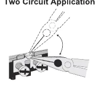
Two-Circuit Application
If you are performing a two-circuit application, you must break off the terminal fin. Refer to the provided diagram for the specific location of the terminal fin to be removed.
Specifications
- Rating: 15 Amp, 125V, 60Hz
- Wire Gauge: #12 AWG and #14 AWG
- AC Outlets: NEMA 5-15R
- Certificate: UL/cUL Listed
Support
For assistance, you can contact Bestten support via email at [email protected] or by phone at 1-800-358-6160 (Mon-Fri 9AM-5PM PST).
Manufacturer information
BESTTEN
Practical help
Common problems
Power is still active during installation
Always turn off power at the circuit breaker or fuse box and test the circuit before touching any wires.
Wire compatibility issues
Use only copper or copper-clad wire. The terminals are designed for #14 or #12 AWG solid copper wire.
Loose connections
Tighten every screw to 14 pound-inch (1.6Nm) of torque and ensure no bare conductors are exposed.
Before use
- Turn off power at the circuit breaker or fuse box
- Verify the use of copper or copper-clad wire
- Ensure wire gauge is #14 or #12 AWG
- Consult a qualified electrician if you are unsure about the installation process
Images and diagrams
- The wiring diagram illustrates the correct connection points for Hot (Black), Neutral (White), and Ground (Green) wires.
- The fin breaking diagram shows where to remove the terminal fin for two-circuit applications.
Model compatibility
- For dry location use only.
- Must be installed in accordance with appropriate electrical codes and regulations.

Manual page author
Michael Turner
Technical manual editor
Reviews PDF manuals for structure, safety notes, and practical product details so readers can find the right information quickly.