Home / Electrical Outlets & Switches
Enerlites 17001-F3 3-Speed Fan and Dimmer Switch Installation Guide
Installation and operation guide for the Enerlites 17001-F3 3-Speed Fan and Full Range Dimmer. Includes wiring instructions, compatibility specifications, and safety warnings.
Quick answers from the manual
Quick answer
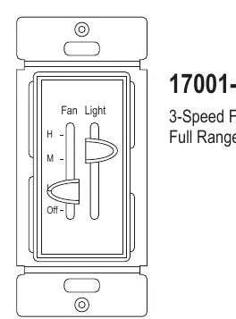
- The Enerlites 17001-F3 is a combination 3-speed fan control and full-range dimmer switch designed for pull-string ceiling fans and standard lighting. p. 1
Key actions
- Wiring the switch p. 1
First start
- Installation sequence p. 1
Problems and fixes
Incompatibility with fan type
The fan control will work with 'pull-string' type fans, but is not compatible with fan types that use remotes or other digital controls.
p. 1Technical specifications
| Parameter | Value | Meaning | Pages |
|---|---|---|---|
| Voltage | 120 VAC 60Hz | Standard operating voltage | p. 1 |
| Incandescent Max | 360W | Maximum incandescent bulb load | p. 1 |
| LED Max | 150W | Maximum LED bulb load | p. 1 |
Where to find it in the PDF
- Installation and Specifications p. 1
Table of contents
Manual images
Click an image to enlargeImportant Information
Before installing the Enerlites 17001-F3, ensure the power is turned off at the circuit breaker. This device is intended for installation in accordance with the National Electric Code and local regulations. It is recommended that a qualified electrician performs the installation. Use copper wire only. Do not connect neutral wires to this controller.
Caution: To reduce the risk of overheating and possible damage to other equipment, do not install this device to control a receptacle, a motor-operated appliance, a fluorescent light fixture, or a transformer-supplied appliance.
Product Description
The 17001-F3 is a combination of a 3-speed fan control and a fully variable dimmer in one unit. It is designed to replace standard switches for easy fan speed and light dimming control without needing to reach for a pull string. It is suitable for multi-gang installations.
Wiring
- Turn off the circuit breaker.
- Connect the HOT wire to the BLACK wire on the switch.
- Connect the FAN wire to the BROWN wire on the switch.
- Connect the LIGHT wire to the RED wire on the switch.
- Connect the GROUND wire to the GREEN wire on the switch.
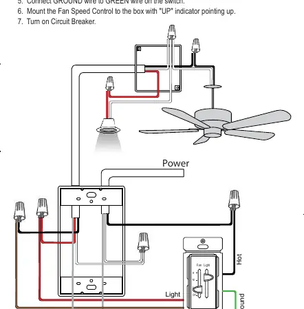
- Mount the Fan Speed Control to the box with the "UP" indicator pointing up.
- Turn on the circuit breaker.
Operation
Fan Control: Slide the lever to any of the 3 speed settings or "Off" for control of the fan only. The lever will have a noticeable stop at each selection.
Light Control: The smooth gliding lever allows you to accurately select the desired light level. To turn off lights completely, slide the lever downwards until you feel the click.
Specifications
- Voltage: 120 VAC 60Hz
- Load Rating (3-Speed Fan): 2.5A
- Incandescent: 360W Max
- LED: 150W Max
- Operating Temperature: 32°F - 104°F
Practical help
Common problems
Fan does not work or is incompatible
Ensure the fan is a 'pull-string' type. This switch is not compatible with fans that use remotes or other digital controls.
Risk of overheating or equipment damage
Do not use this switch to control a receptacle, motor-operated appliance, fluorescent light fixture, or transformer-supplied appliance.
Before use
- Turn off power at the circuit breaker
- Verify the fan is a pull-string type
- Ensure you are using copper wire only
- Do not connect neutral wires to the switch
Specs in practice
- Incandescent Load
- Maximum lighting load is 360W.
Images and diagrams
- The wiring diagram illustrates the connection of the Hot, Fan, Light, and Ground wires to the switch.
- The switch diagram identifies the Fan control lever (H, M, Off) and the Light control lever.
Model compatibility
- Compatible with LED, CFL, Incandescent, and Halogen bulbs.
- Not compatible with fans using remotes or digital controls.
- Do not use with low-voltage ballasts or drivers.

Manual page author
David Miller
Documentation analyst
Organizes user manual content into clear summaries, with attention to model details, product context, and everyday usability.