Electronics / Collaboration Devices
User Manual for BirdDog 227RGBW-CTL RGBW LED Control System
Quick guide for the BirdDog 227RGBW-CTL LED controller. Learn how to connect, program, and operate your RGBW lighting system with this manual.
Quick answers from the manual
Quick answer
- The BirdDog 227RGBW-CTL is a 2.4G touch screen controller for RGBW LED strips. It supports 12V-24V DC input, 6A per channel, and features 20 automatic modes. p. 1
Key actions
- Pairing the remote: Switch power off, switch on, and press key 5 once within 3 seconds. p. 1
- Clearing the code: Switch power off, switch on, and long press key 5 within 3 seconds. p. 1
Problems and fixes
Remote not working
Perform the code matching procedure.
p. 1Show 2 more answers Show less
Technical specifications
| Parameter | Value | Meaning | Pages |
|---|---|---|---|
| Working Voltage | DC12V~24V | Required power supply input | p. 1 |
| Max load per channel | 6A | Maximum current capacity per color channel | p. 1 |
| Telecontrol distance | 30 meters | Wireless range | p. 1 |
Where to find it in the PDF
- Product Overview and Technical Data p. 1
Table of contents
Quick Guide
The BirdDog 227RGBW-CTL is a high-performance 2.4G touch screen remote controller designed for RGBW LED strips and modules. It features 640,000 colors, 20 automatic changing modes, and a memory function that resumes previous settings after power loss.
Technical Specifications
- Working Voltage: DC 12V-24V
- Max Load per Channel: 6A
- Output Connection: Common anode
- Telecontrol Distance: 30 meters
- Remote Power: 2x AAA batteries
- Dimensions (Remote): 110 x 52 x 20 mm
- Dimensions (Controller): 85 x 45 x 23 mm
Function of Keys
The remote features a touch ring for color selection and dedicated buttons for:
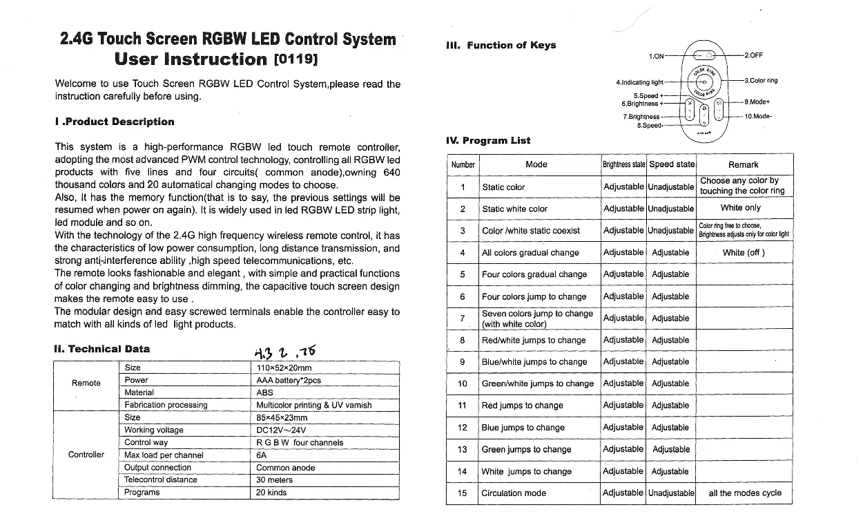
- ON/OFF: Power control.
- Color Ring: Select colors.
- Speed +/-: Adjust speed of dynamic modes.
- Brightness +/-: Adjust light intensity.
- Mode +/-: Cycle through 20 automatic programs.
Connection
The controller uses a common anode connection. Ensure the power supply voltage matches the controller requirements (12V-24V DC). Connect the LED load wires to the corresponding W, B, G, R, and + terminals on the controller.
Programming
Code Matching
For a new kit, the remote must be paired with the controller:
- Correctly connect the power supply, LED controller, and LED load.
- Switch off the power, then switch it on again.
- Press the key 5 once within 3 seconds of powering on.
- The LED light will blink twice slowly to confirm successful pairing.
Code Clearing
- Switch off the power, then switch it on again.
- Long press the key 5 within 3 seconds of powering on.
- The LED light will blink nine times swiftly to confirm the code has been cleared.
Safety and Attention
- Ensure the input voltage of the power supply is compatible with the controller.
- Do not connect wires while the power is on.
- Switch on only after verifying correct connections and ensuring there are no short circuits.
- Keep fingers off the touch ring when installing batteries to maintain sensitivity.
- Avoid using the controller in areas with strong electromagnetic interference or large metal surfaces, as this may reduce the remote control distance.
Manufacturer information
BirdDog
Practical help
Common problems
Remote does not control the lights
The remote may need to be paired with the controller. Follow the 'Code matching' procedure.
Low touch sensitivity on the remote
Reinstall the batteries. Ensure your fingers are not touching the touch ring during battery installation.
Remote distance is very short
Ensure the controller is not placed near large metal areas or sources of strong electromagnetic waves.
Before use
- Verify the power supply provides 12V-24V DC.
- Ensure the LED strip is a common anode type.
- Install 2x AAA batteries in the remote.
- Check all wiring connections for short circuits before powering on.
- Ensure the controller is not installed in a shielded metal enclosure.
Show more Show less
Specs in practice
- Common Anode
- The LED strip must share a positive (+) connection for all color channels.
- Max load 6A per channel
- The maximum current the controller can handle per color channel (W, B, G, R).
Images and diagrams
- The connection diagram shows the power supply (AC to DC) connected to the controller's power input, and the LED strip connected to the W, B, G, R, and + terminals.
Model compatibility
- Compatible with RGBW LED strips and modules using common anode configuration.

Manual page author
David Miller
Documentation analyst