HVAC / Water Heaters
Installation and Operating Instructions for Bosch AquaStar 125B Water Heater
A comprehensive installation and operating guide for the Bosch AquaStar 125B LPL and 125B NGL tankless water heaters. This manual covers safety procedures, mounting, venting, gas and water connections, maintenance, and troubleshooting.
Table of contents
Manual images
Click an image to enlargeQuick Guide from the Manual
The Bosch AquaStar 125B is a tankless, instantaneous gas water heater. Safety First: If you smell gas, do not attempt to light the appliance, do not touch electrical switches, and do not use phones in the building. Immediately evacuate and call your gas supplier from a neighbor's phone. Installation and service must be performed by a qualified installer or service agency.
Installation Requirements
The heater must be installed in a location with adequate combustion air and proper venting. It is not approved for mobile homes, RVs, boats, or outside installation. Do not install in bathrooms, bedrooms, or unvented closets. Ensure the unit is installed as close to a vent or chimney as possible.
Mounting and Clearances
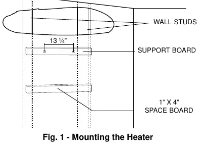
The unit must be mounted on a wall using the provided L-shaped hooks. If mounting on a stud wall with plasterboard, use a support board (1x4 or 1/2 inch plywood) across the studs. Minimum clearances are: Top 12 inches, Front 4 inches, Back 0 inches, Sides 4 inches, and Bottom 12 inches.
Gas and Water Connections
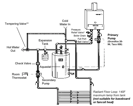
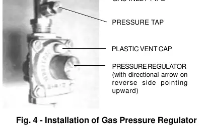
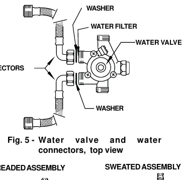
The unit is supplied with a gas pressure regulator that must be installed before connecting the gas supply. Ensure the gas type (Natural Gas or Liquid Propane) matches the rating plate. For water connections, the cold water inlet is on the right and the hot water outlet is on the left. Use copper piping for at least three feet before and after the heater. A pressure relief valve (PRV) must be installed on the hot water line.
Operating Instructions
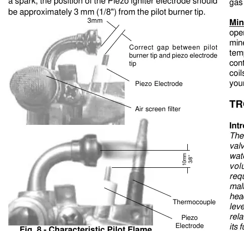
Before operation, ensure the system is filled with water. To light the pilot: turn off the gas valve, wait 5 minutes, depress the pilot button, and push the piezo igniter button repeatedly. Hold the pilot button for at least 10 seconds after the flame ignites. Once the pilot is lit, depress the ON button to enable the main burner.
Maintenance and Troubleshooting
The heater should be checked and cleaned annually. This includes inspecting the vent assembly, pilot assembly, and main burner. If the pilot light fails to light, check the gas supply and ensure the pilot button is fully depressed. If the burners fail to ignite, check for low water flow (minimum 1.8 GPM required) or a dirty inlet filter. Mineral scale build-up may require flushing the heating coils with a descaling solution.
Manufacturer information
Bosch
Practical help
Common problems
Pilot light will not light
Check if the gas cock is open and ensure the gas valve button is pushed in to the 'PILOT' position.
Burners do not ignite when hot water is turned on
Verify water flow rate is at least 1.8 GPM, check for a dirty cold water inlet filter, or ensure the gas valve button is in the 'Burner' position.
Water is not hot enough
Decrease water flow rate, move gas control slide to the right, or check for insufficient gas pressure.
Pilot light goes out during or after use
Check for low gas pressure, dirty pilot, or poor thermocouple connection.
Before use
- Verify the gas type (LPG or NG) matches the unit rating plate.
- Ensure the gas pressure regulator is installed correctly.
- Check that the vent pipe is 5 inches in diameter and at least 6 feet high.
- Ensure water pressure is between 30-50 psi for well systems.
- Confirm all clearances (Top 12", Front 4", Sides 4") are met.
- Flush water lines to remove debris before connecting.
Specs in practice
- Water Connection
- 1/2 inch thread fitting.
- Min. Water Flow
- 1.8 gallons per minute required to activate burners.
Images and diagrams
- Fig 10 shows the internal layout including the heat exchanger, gas valve, and pilot assembly.
- Fig 11 provides a detailed parts list and exploded view of internal components.
Model compatibility
- Not approved for mobile homes, recreational vehicles (RV), or boats.
- Not designed or approved for outside installation.
- Not certified for space heating only; must be used in combination with potable water.

Manual page author
Emily Carter
User documentation editor
Prepares concise manual descriptions and highlights the most useful setup, operation, and maintenance information for readers.