HVAC / Water Heaters
Installation and Operating Instructions for Bosch AquaStar 125FX Water Heater
Quick guide for the Bosch AquaStar 125FX tankless water heater. Includes installation, venting, gas/water connection, operation, maintenance, and troubleshooting steps.
Table of contents
Manual images
Click an image to enlargeQuick guide from the manual
This manual provides essential installation and operating instructions for the Bosch AquaStar 125FX tankless water heater. This unit is designed for heating potable water only and is not approved for space heating, manufactured homes, or recreational vehicles. Always ensure the unit is installed by a qualified professional in accordance with local codes.
Safety Information
If you smell gas:
- Close the gas valve and open windows.
- Do not attempt to light any appliance.
- Do not touch any electrical switch or use any phone in the building.
- Immediately call your gas supplier from a neighbor's phone.
- If the gas supplier cannot be reached, call the fire department.
General Safety:
- Do not store flammable liquids or vapors near the heater.
- The heater must be electrically grounded.
- Do not install in bathrooms, bedrooms, or unvented closets.
- Ensure the unit is not installed in an area where it could freeze.
Installation
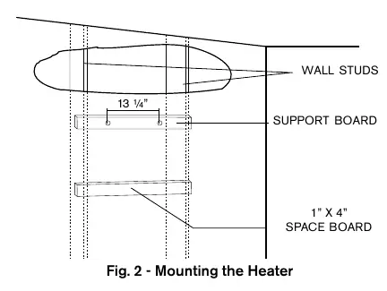
Mounting: The heater is designed for wall mounting. Secure the two L-shaped hooks provided, spaced 13 1/4 inches apart. Do not install on carpeted walls or over combustible floor coverings.
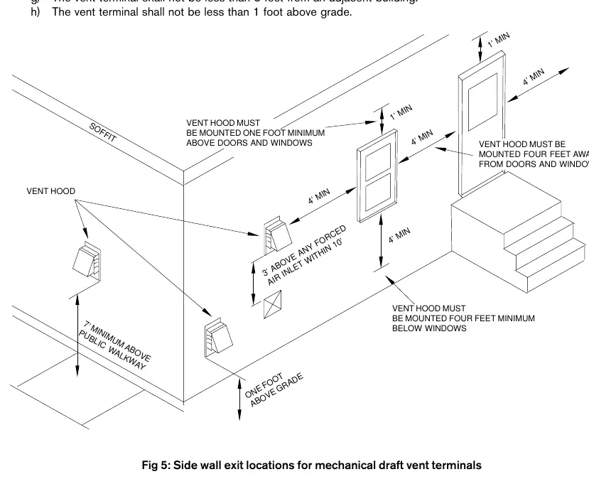
Venting: The unit requires a 4-inch single-wall vent pipe (stainless steel AL29-4C or galvanized steel, minimum 26 gauge). The maximum vent length is 15 feet with two 90-degree elbows. The system must be sealed gas-tight.
Gas Connections: The unit is supplied with a gas pressure regulator that must be installed before the gas supply line. Ensure the gas pipe is sized correctly based on the distance from the meter (see manual for sizing charts).
Water Connections: Use copper piping for at least three feet before and after the heater. The cold water inlet is on the right, and the hot water outlet is on the left. Ensure the water inlet filter is clean and the system is flushed before connection.
Operation
Lighting: Ensure the system is filled with water. Set the On/Off switch to the 'On' position. Open a hot water faucet to activate the flow; the automatic ignition system will ignite the pilot and then the main burners.
Temperature Adjustment: Use the temperature adjustment knob located beneath the main gas controls. Turning it clockwise increases the temperature (and decreases flow), while turning it counter-clockwise decreases the temperature (and increases flow).
Maintenance
Annual Maintenance: The heater should be checked and cleaned annually. This includes inspecting the vent system, pilot assembly, and main burner. The water valve should be lubricated every two years and rebuilt every 3-5 years depending on water conditions.
Troubleshooting
If the unit fails to operate, check the following:
- No spark at pilot: Check the On/Off switch, electrical connections, and water flow rate.
- Pilot sparks but no ignition: Check for air in the gas line, ensure the gas cock is open, and verify the gas regulator is not locked.
- Main burners go out: Check for deficient flue gas exhaustion or unbalanced water pressure.
- Water too hot/not hot enough: Adjust the temperature knob or check for plumbing crossovers.
Manufacturer information
Bosch
Practical help
Common problems
No spark at pilot
Ensure On/Off switch is 'On', check electrical connections, and verify water flow is sufficient to activate the microswitch.
Pilot sparks but no ignition
Bleed air from the gas line, ensure gas cock is open, and check if the gas regulator is locked.
Main burners go out during use
Check for deficient flue gas exhaustion or unbalanced water pressure between cold and hot lines.
Exhaust fan does not operate
Check the fuse, electrical connections, and microswitch adjustment.
Before use
- Ensure the system is filled with water.
- Verify the gas supply is connected and pressure is correct.
- Check that the unit is properly vented with a 4-inch pipe.
- Ensure electrical power is connected and the unit is grounded.
- Check for gas leaks using soapy water (never use a flame).
Specs in practice
- Water Pressure
- 18 PSI minimum to 150 PSI maximum.
- Vent Diameter
- 4 inches (single wall).
Images and diagrams
- Fig 9: Wiring diagram for electrical connections.
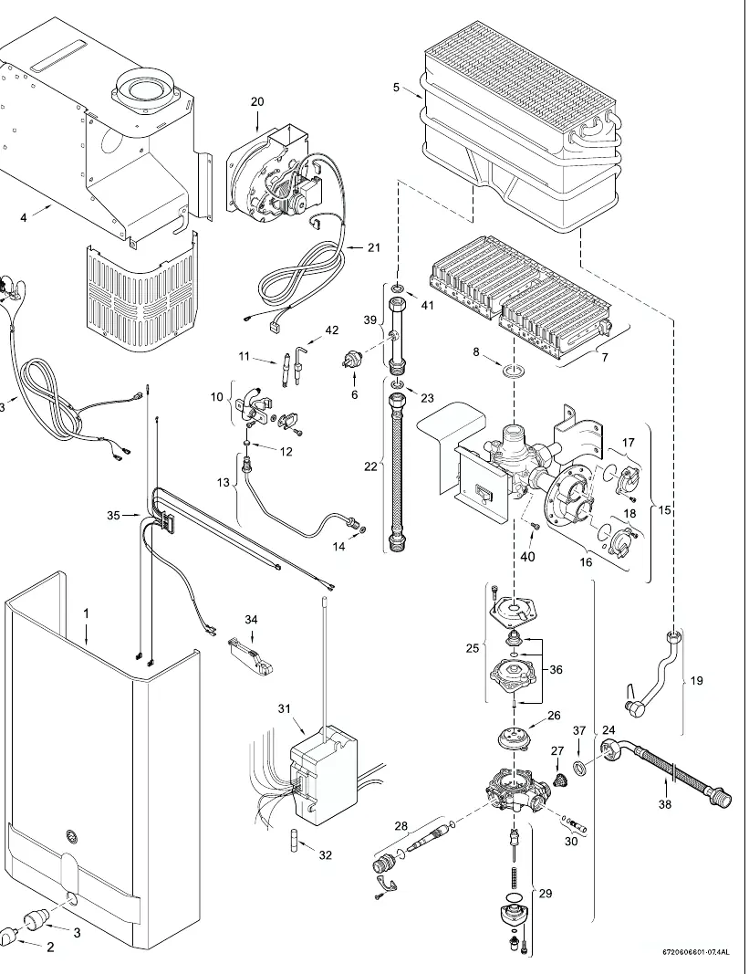
- Fig 15: Exploded view of internal components.
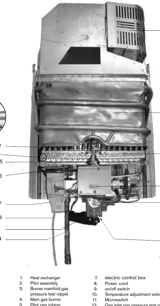
- Fig 16: Interior components diagram and parts list.
Model compatibility
- Not approved for space heating.
- Not approved for manufactured homes, RVs, or boats.
- Suitable for heating potable water only.

Manual page author
Emily Carter
User documentation editor
Prepares concise manual descriptions and highlights the most useful setup, operation, and maintenance information for readers.