HVAC / Water Heaters
Bosch 125BO Outdoor Tankless Water Heater
Quick guide for the Bosch 125BO outdoor tankless water heater. Includes installation, operation, maintenance, and troubleshooting steps.
Table of contents
Manual images
Click an image to enlargeQuick guide from the manual
The Bosch 125BO is an outdoor-only tankless water heater designed for heating potable water. It is not approved for indoor use, space heating, or for use in mobile homes, RVs, or boats. Important: If you smell gas, immediately close the gas valve, do not attempt to light any appliance, do not use electrical switches or phones in the building, and call your gas supplier or fire department from a neighbor's phone.
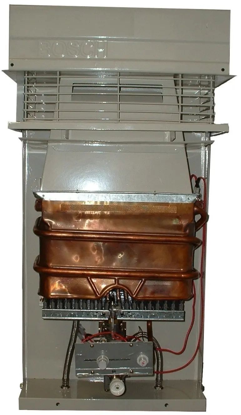
Appliance overview
The unit features piezo ignition, stainless steel burners, and a built-in draft diverter. It modulates burner output based on water flow demand. It is available in Natural Gas (NG) and Liquefied Petroleum (LP) gas models.
Installation
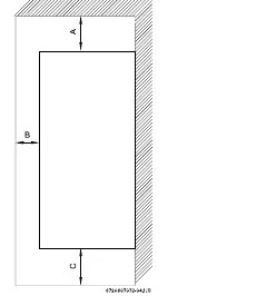
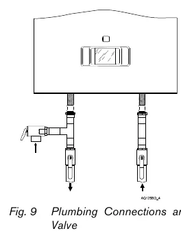
Installation must be performed by a licensed plumber or gas fitter. Clearances: The unit requires specific clearances for safe operation: 3 ft from the top, 4 ft from the front and sides, and 1 ft from the bottom. It must be installed on an external wall. If installing on vinyl siding, a 6' x 4' area must be covered with non-plastic material. Gas connections: Ensure the gas supply line is sized correctly for the 117,000 BTUH demand. A manual gas shut-off valve must be installed on the supply line. Water connections: Use 1/2 inch piping. It is recommended to use copper or stainless steel flex lines for at least three feet before and after the heater. Install full port valves on both cold inlet and hot outlet lines to facilitate servicing.
Operation
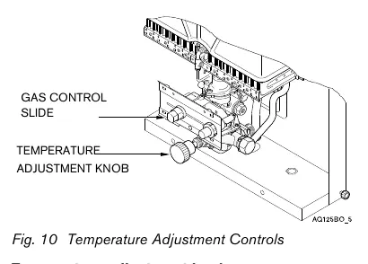
Lighting: Ensure the gas valve is off, wait 5 minutes to clear gas, open the sliding viewer window, slide the gas valve button to the right, and depress the button while hitting the piezo igniter. Hold the button for at least 15 seconds after the pilot lights. Temperature adjustment: Use the temperature adjustment knob to control flow capacity (clockwise increases temperature, counter-clockwise decreases it) or the gas control slide to adjust gas flow to the burners.
Maintenance
Annual: Inspect inlet water filter screen, pilot assembly, and burner assembly. Every 2 years: Lubricate and clean the water valve. Every 3-5 years: Rebuild the water valve and clean/replace the pilot orifice. If the heater is used at high temperature settings with hard water, periodic descaling of the heating coils may be required.
Troubleshooting
If the pilot will not light, check for air in the gas line or ensure the manual gas valve is open. If the pilot lights but does not stay on, ensure the gas valve button is held down long enough, check the thermocouple, and ensure the electromagnet connection is tight. If burners do not ignite, verify the pilot is lit and check for sufficient water flow (minimum 0.5 GPM).
Manufacturer information
Bosch
Practical help
Common problems
Pilot will not light
Bleed air from the gas line by holding the gas valve button while hitting the piezo igniter. Ensure the manual gas shut-off valve is open.
Pilot lights but does not stay on
Ensure the gas valve button is held down for at least 15 seconds. Check that the pilot flame is blue and hitting the thermocouple tip. Tighten the electromagnet connection.
Burners do not ignite with water flow
Verify the pilot is lit. Check for water flow restrictions (clogged aerators or inlet filter). Ensure the temperature adjustment knob is set correctly.
Hot water temperature fluctuates
Check for plumbing cross-overs. Ensure the inlet water pressure is sufficient (30-50 psi for well systems). Check for clogged aerators or shower heads.
Before use
- Verify the gas type (LP or NG) matches your supply.
- Ensure the installation location is outdoors and meets all clearance requirements.
- Install a manual gas shut-off valve on the supply line.
- Install a union on water connections for easy servicing.
- Ensure the unit is properly grounded electrically.
- Check that the flue terminal is clear of combustible materials.
Specs in practice
- Maximum flow rate
- 3.7 GPM at a 45°F rise.
- Minimum water flow
- 0.5 GPM required to activate the heater.
- Gas connection
- 3/4 inch diameter required.
- Water connection
- 1/2 inch diameter for both inlet and outlet.
Images and diagrams
- Fig 12: Functional scheme showing internal components like the heat exchanger, water valve, and gas control.
- Fig 13: Exploded view of components for parts identification and maintenance.
Model compatibility
- Not approved for indoor use.
- Not approved for space heating purposes.
- Not approved for mobile homes, RVs, or boats.
- Not for use with high-temperature booster systems.

Manual page author
David Miller
Documentation analyst
Organizes user manual content into clear summaries, with attention to model details, product context, and everyday usability.