Tools / Power Tools
Parts Diagram for Bosch GHO 18V-LI Cordless Planer
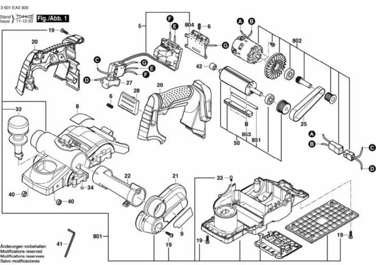
Access the official exploded view parts diagram for the Bosch GHO 18V-LI cordless planer. Use this document to identify internal components, assembly structure, and specific part numbers for maintenance and repair.
Table of contents
Parts Diagram Overview
This document provides an exploded view of the Bosch GHO 18V-LI cordless planer. It is intended for use by technicians and owners to identify individual components, understand the assembly structure, and locate specific part numbers required for maintenance or repair.
Using the Exploded View
The diagram illustrates the internal and external components of the planer, showing how they fit together. When performing repairs or maintenance, use this guide to:
- Identify Parts: Locate specific components such as the motor, blade drum, belt, and housing elements.
- Understand Assembly: Observe the sequence of assembly to ensure correct reinstallation of parts.
- Locate Hardware: Identify the placement of screws, bearings, and other small fasteners.
Maintenance and Repair Notes
When using this diagram for servicing your tool, keep the following in mind:
- Safety First: Always remove the battery pack before attempting any disassembly or maintenance on the cordless planer.
- Organization: Keep track of small parts (screws, washers, bearings) as you remove them. The diagram helps verify the correct location for each item during reassembly.
- Replacement Parts: Use the visual reference to identify the specific part needed. Ensure you source genuine replacement parts to maintain the tool's performance and safety standards.
- Professional Service: If you are unsure about the disassembly or reassembly process, or if the tool requires internal motor or electrical work, it is recommended to consult an authorized Bosch service center.
Manufacturer information
Bosch
Practical help
Common problems
Difficulty reassembling the tool
Refer to the exploded view diagram to verify the correct order and orientation of internal components, particularly the motor and blade drum assembly.
Identifying a specific screw or fastener
The diagram labels various fasteners and small parts. Match the physical part to its location in the exploded view to ensure the correct replacement is used.
Before use
- Ensure the battery is removed before starting any maintenance.
- Clear a clean, well-lit workspace to lay out parts.
- Have the correct tools (e.g., screwdrivers, hex keys) ready.
- Use the diagram to identify the specific area of the tool requiring attention.
Specs in practice
- 3 601 EA0 300
- This is the specific machine number (model code) for the Bosch GHO 18V-LI, essential for ordering the correct replacement parts.
Images and diagrams
- The diagram shows an exploded view, meaning components are separated to show how they connect.
- Parts are grouped by their assembly location (e.g., motor assembly, housing, blade drum).
- Lines and arrows indicate the direction of assembly for various components.
Model compatibility
- This parts diagram is specific to the Bosch GHO 18V-LI model (Machine No: 3 601 EA0 300). Ensure your tool matches this code before ordering parts.

Manual page author
Emily Carter
User documentation editor
Prepares concise manual descriptions and highlights the most useful setup, operation, and maintenance information for readers.