Garden / Outdoor
Parts List for Bosch GRT 18V-33 Grass Trimmer
View the official parts list and exploded diagrams for the Bosch GRT 18V-33 cordless grass trimmer. Identify components, assembly parts, and torque specifications for maintenance and repair.
Table of contents
Manual images
Click an image to enlargeImportant information from the document
This document provides the official exploded view diagrams and parts list for the Bosch GRT 18V-33 cordless grass trimmer. It is intended for identifying components, understanding the assembly structure, and performing repairs. It includes specific torque values required for reassembly.
Exploded View and Components
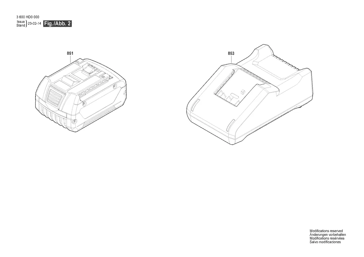
The document contains detailed diagrams (Fig. 1 and Fig. 2) illustrating the assembly of the trimmer. These diagrams identify the various components of the unit, including the motor housing, handle assembly, cutting head, and the battery/charger system. Use these diagrams to locate specific part numbers and understand how the components fit together.
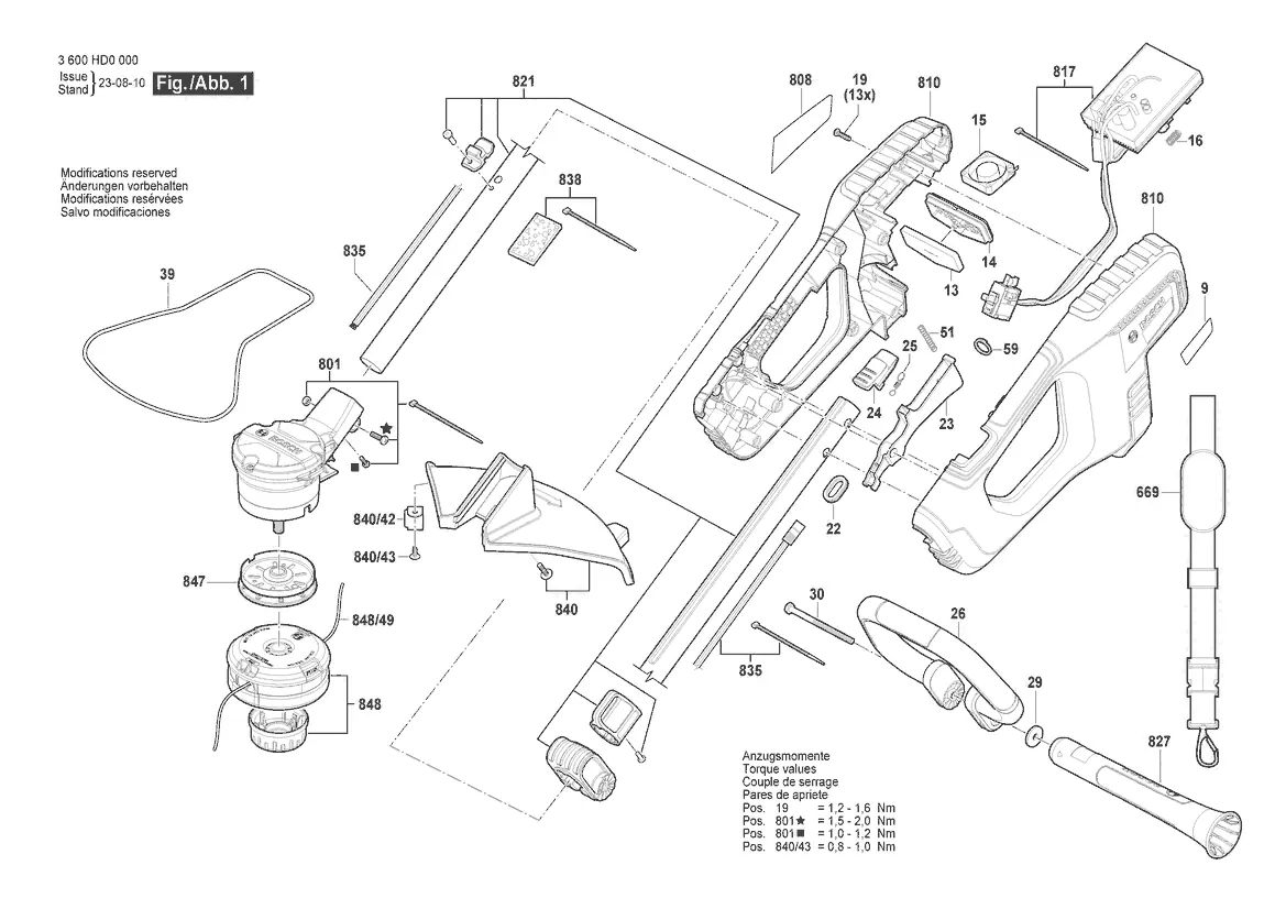
Torque Specifications
When reassembling the grass trimmer, it is critical to use the correct torque values to ensure the integrity of the housing and components. Refer to the following specifications provided in the diagram:
- Pos. 19: 1.2 - 1.6 Nm
- Pos. 801 (star symbol): 1.5 - 2.0 Nm
- Pos. 801 (square symbol): 1.0 - 1.2 Nm
- Pos. 840/43: 0.8 - 1.0 Nm
Maintenance and Repair
Always ensure the battery is removed from the tool before performing any disassembly or maintenance. Use the exploded view to identify the correct position of screws and parts. If you require further assistance or spare parts, you can visit the official Bosch service website at https://www.boschtoolservice.com.
Official resources from the manual
Manufacturer information
Bosch
Practical help
Common problems
Incorrect torque during assembly
Ensure all screws are tightened to the specified torque values (0.8 - 2.0 Nm depending on the position) to prevent damage to the plastic housing or internal components.
Before use
- Verify all parts are present according to the exploded view before starting assembly.
- Ensure the battery is removed from the tool before performing any maintenance or disassembly.
- Use a calibrated torque wrench to tighten screws to the values specified in the diagram.
Specs in practice
- Torque values
- The specific tightening force required for screws to ensure the structural integrity of the tool assembly.
Images and diagrams
- Fig. 1 shows the main assembly of the grass trimmer, including the motor, handle, and cutting head components.
- Fig. 2 illustrates the battery and charger components.

Manual page author
Michael Turner
Technical manual editor
Reviews PDF manuals for structure, safety notes, and practical product details so readers can find the right information quickly.