HVAC / Water Heaters
Installation Guide for Bradford White 120T Series Water Heater
Quick installation guide for the Bradford White 120T Series water heater. Includes venting requirements, gas pressure specifications, condensate line setup, and service clearance guidelines.
Table of contents
Quick guide from the manual
This document serves as an installation checklist for the Bradford White 120T Series water heater. Before proceeding, ensure you have the full installation and operation manual available. Key requirements include proper venting, gas pressure regulation, and condensate line management.
Product Handling
Carefully uncrate the heater. Use a pallet jack to move the unit into place. Do not use the venting pipes as handles. It is recommended to place the heater on a 2-inch (5 cm) high installation pad.
Electrical Requirements
The unit requires a dedicated 120-volt line. Ensure the power is properly polarized and that the heater is correctly grounded.
Venting Requirements
All venting must adhere to specific length and diameter limits. Proper support is mandatory for the venting pipe, with supports required every 5 feet (1.5 m) vertically and 3 feet (0.9 m) horizontally. Terminations must be positioned to prevent re-circulation. Medium to long sweep 90-degree elbows are recommended.
Gas Requirements
Supply the correct gas piping size: 1-inch (2.5 cm) NPT or equivalent is required for 399,999 btu/hr and 499,999 btu/hr models. Install a properly sized regulator to ensure adequate gas volume. Operating gas pressure must be 7 inches (1741.9 Pa) W.C., and standby pressure must remain below 14 inches (3483.8 Pa) W.C.
Condensate Requirements
The condensate line must be sized and sloped correctly to a suitable drain (1/4 inch per foot or 0.6 cm per 0.3 m). A condensate trap must be constructed as close to the water heater as possible. Protect the line from freezing. Use the provided rubber coupler (p/n 239-53385-00) to connect the condensate line to the condensate elbow.
Service and Maintenance
Ensure adequate space is provided for servicing. Leave sufficient room to access the bottom pressure switch and maintain at least 18 inches (45.7 cm) of overhead clearance to remove power anode rods. For technical support, contact Bradford White Technical Service at 800 334-3393.
Practical help
Common problems
Venting pipe damage during installation
Do not use venting pipes as handles when moving the unit with a pallet jack.
Condensate line freezing
Protect the condensate line from freezing conditions in the installation environment.
Gas pressure instability
Ensure a properly sized regulator is installed; operating pressure must be 7 inches W.C.
Before use
- Ensure a 2-inch installation pad is used.
- Verify 120V dedicated power supply is polarized and grounded.
- Check that venting supports are installed every 5 ft vertically and 3 ft horizontally.
- Confirm gas piping is 1-inch NPT.
- Ensure condensate line is sloped 1/4 inch per foot.
Specs in practice
- Operating Gas Pressure
- 7 inches W.C. required during operation.
- Standby Gas Pressure
- Must remain below 14 inches W.C.
- Overhead Clearance
- 18 inches minimum required for anode rod removal.
Images and diagrams
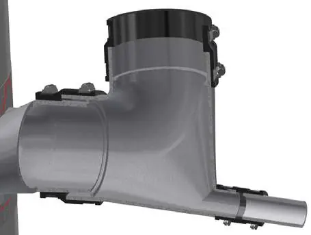
- The diagram illustrates the condensate trap assembly and vent connection.
- Apply clear RTV sealant around the male end of the exhaust pipe before installing the condensate elbow.
- Use the provided rubber coupler (p/n 239-53385-00) and tighten hose clamps to ensure no leaks.
Model compatibility
- Compatible with 4-inch and 6-inch PVC, ABS, and CPVC venting.
- Maximum venting lengths vary by pipe diameter (120 ft for 4-inch, 240 ft for 6-inch).

Manual page author
David Miller
Documentation analyst
Organizes user manual content into clear summaries, with attention to model details, product context, and everyday usability.