Electronics / Two-Way Radios
Operating Manual for Braun LT 470 / LT 472 Linear-Transverter
Quick guide for the Braun LT 470 / LT 472 2-m/70-cm Linear-Transverter. Includes connection instructions, operation, technical specifications, and alignment procedures for qualified personnel.
Quick answers from the manual
Quick answer
- The Braun LT 470 / LT 472 is a linear transverter for 2-m/70-cm amateur radio bands. It requires connection to a 2-m transceiver and 50 Ohm antennas. p. 1, 5
Key actions
- Connect the 2-m transceiver to the '2m RX/TX' port using the supplied coaxial cable. p. 5
- Adjust the 2m Input Attenuator to match the output of your 2-m transceiver. p. 6
Problems and fixes
Noise level too high
Reduce gain using the RX-GAIN control.
p. 7Technical specifications
| Parameter | Value | Meaning | Pages |
|---|---|---|---|
| Frequency Range | 430 - 440 MHz | Operating frequency band | p. 9 |
| Power Consumption | 25 VA (receive), 50 VA (transmit) | Electrical power usage | p. 9 |
Where to find it in the PDF
- Front Panel p. 1, 7
- Rear Connections p. 5
- Alignment Points p. 11, 13
Table of contents
Quick guide from the manual
The Braun LT 470 / LT 472 is a linear transverter designed for 2-m/70-cm amateur radio operation. This document provides instructions for installation, operation, and technical alignment. Note: Alignment and service work should only be performed by qualified technical personnel.
Connections
All connections are located on the rear of the unit:
- Power Line: Connect the supplied power cable to the 220 V AC connector.
- Transceiver Connection: Connect the 2-m transceiver to the unit. If using the SE 402, use the supplied cable. For other transceivers, ensure proper relay switching via the 'External' socket.
- RF Interconnection: Use the supplied coaxial cable to connect the 2-m transceiver to the '2m RX/TX' connector. Ensure an impedance of 50 Ohm.
- Antennas: Connect the 70-cm and 2-m antennas to their respective 50 Ohm connectors.
Operation
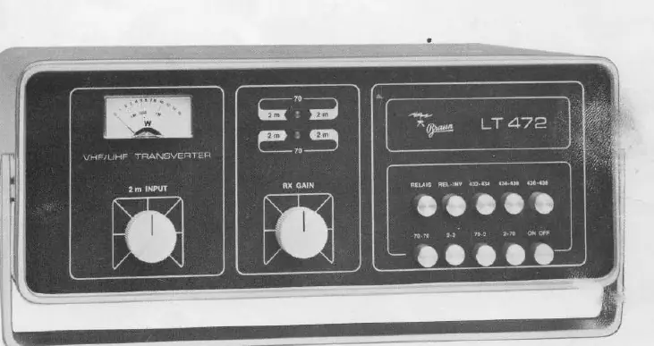
Controls are located on the front panel:
- On/Off Switch: Combined with the frequency mode switch.
- Frequency Mode Buttons: Select the desired frequency range (432-434, 434-436, 436-438 MHz) and relay settings.
- 2m Input Attenuator: Used to adjust the drive of the linear amplifier based on the output of the 2-m transceiver.
- RX Gain: Adjusts the gain of the receive converter.
Service and Alignment
Warning: Alignment should only be performed by qualified personnel using appropriate test equipment, including an RF-mV-meter, sweep generator, spectrum analyzer, and frequency counter.
The manual provides detailed procedures for:
- Measuring voltages at specific test points.
- Adjusting quiescent current for the exciter and power amplifier.
- Oscillator frequency corrections.
- Receiver and exciter alignment steps.
Technical Specifications
Key parameters for the LT 470 / LT 472:
- Frequency Range: 430 - 440 MHz.
- Noise Figure: 6 dB.
- RF Output: 2.5 W (AM), 10 W (FM), 5 W (SSB), 10 W (CW/RTTY).
- Power Consumption: 25 VA (receive), 50 VA (transmit).
- Dimensions: 307 mm (W) x 117 mm (H) x 272 mm (D).
- Weight: 6.4 kg.
Manufacturer information
Braun
Practical help
Common problems
High noise level
Use the RX-GAIN control to reduce gain by up to 6 dB without affecting sensitivity.
Incorrect relay switching
Ensure the 'External' socket is correctly wired for your specific 2-m transceiver.
Impedance mismatch
Ensure all antenna and transceiver connections are designed for 50 Ohm impedance.
Before use
- Verify power supply is 220 V AC.
- Ensure 2-m transceiver is connected to the '2m RX/TX' port.
- Check that all antenna connections are 50 Ohm.
- Ensure the 2-m transceiver output is adjusted to match the transverter input requirements.
Images and diagrams
- Figure 1: Rear panel showing power and antenna connections.
- Figure 2: Front panel controls including RX Gain and Mode buttons.
- Figure 3: Internal view showing alignment points (L, C, R components).
- Figure 4: Internal view of the final stage for power amplifier alignment.
Model compatibility
- Designed for use with 2-m transceivers.
- Requires 50 Ohm antenna systems.
- Alignment requires specific test equipment (RF-mV-meter, sweep generator).

Manual page author
David Miller
Documentation analyst
Organizes user manual content into clear summaries, with attention to model details, product context, and everyday usability.