Electronics / Digital Photo Frames
Braun 58077 Outdoor LED Wall Pack and Security Light User Manual
Quick guide for the Braun 58077 Outdoor LED Wall Pack. Includes installation steps, wiring diagrams, safety warnings, and technical specifications for proper setup.
Table of contents
Manual images
Click an image to enlargeQuick guide from the manual
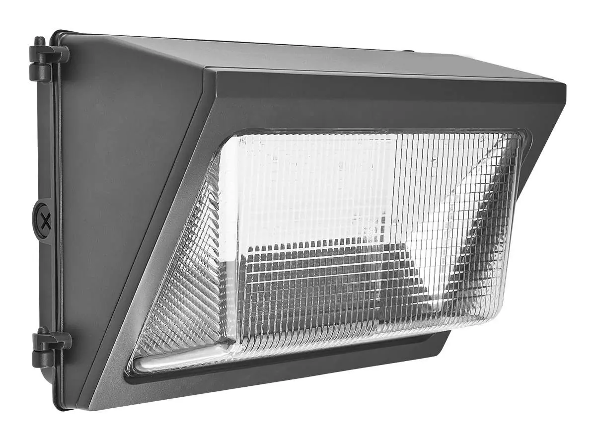
The Braun 58077 is an outdoor LED wall pack designed for security lighting. Important: This product must be installed by a qualified electrician in accordance with local electrical codes. It requires a power supply of 120-277 VAC and must be mounted at least 6' 6" off the ground. Do not connect to dimmer packs, occupancy sensors, or timing devices unless specifically compatible.
Safety Information
To prevent serious injury or death from electric shock, follow these precautions:
- Power Off: Always disconnect power at the fuse or circuit breaker before installation or maintenance.
- Mounting: Do not mount against flammable surfaces. Ensure the mounting surface is structurally sound to support the fixture's weight.
- Environment: Intended for outdoor use. Do not use in areas with limited ventilation or high ambient temperatures.
- Personal Safety: Wear safety glasses and heavy-duty work gloves during installation.
- Pacemakers: Individuals with pacemakers should consult a physician before installation due to potential electromagnetic interference.
Installation Instructions
Before starting, ensure the installation surface has no hidden utility lines.
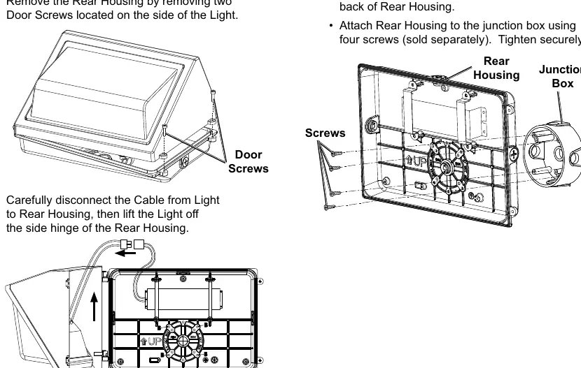
- Remove Rear Housing: Remove the two door screws on the side of the light to separate the housing.
- Disconnect Cable: Carefully disconnect the cable from the light to the rear housing and lift the light off the side hinge.
- Mounting:
- Junction Box: Attach the junction box to the wall, remove pre-cast locators on the rear housing, and secure the housing to the junction box using four screws.
- Direct to Wall: Use the rear housing as a template to drill three mounting holes. Secure to the wall using appropriate screws and seal screw heads with waterproofing sealant.
- Wiring: Connect the light to the power source as detailed in the wiring diagram section.
- Final Assembly: Reconnect the cable and light to the rear housing. Crucial: Remove the two drain plugs from the bottom of the light housing before closing the door. Secure the door with the two door screws.
Wiring Diagram
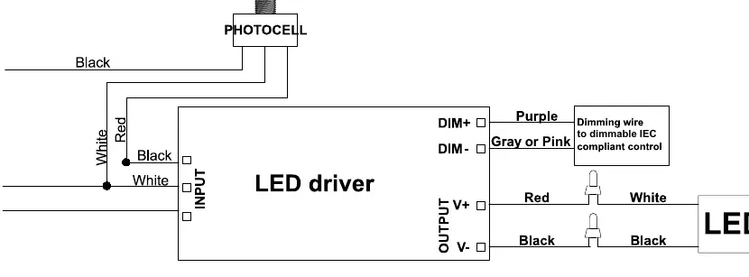
The fixture includes a photocell and an LED driver. The wiring involves connecting the Line (L), Neutral (N), and Ground (G) wires to the input side of the LED driver. Dimming wires (Purple for DIM+, Gray or Pink for DIM-) are provided for connection to dimmable IEC-compliant controls.
Maintenance
Inspect the fixture before every use. Do not use if parts are loose or damaged. Keep the assembly area clean and well-lit during any service. If labels or nameplates become unreadable, contact Harbor Freight Tools for replacements.
Manufacturer information
Braun
Practical help
Common problems
Light does not illuminate
Verify power supply is 120-277 VAC, check that the breaker is on, and ensure all wiring connections are secure.
Fixture is unstable
Ensure the mounting surface is structurally sound and all screws are tightened to recommended torque.
Before use
- Verify voltage is 120-277 VAC.
- Ensure power is disconnected at the breaker box.
- Check that the mounting surface is not flammable.
- Confirm the mounting surface can support the fixture weight.
- Wear safety glasses and heavy-duty work gloves.
- Ensure all parts are present and undamaged.
Specs in practice
- Electrical Rating
- 120-277 VAC / 50/60 Hz / 50W. Ensure your power supply matches these requirements.
Images and diagrams
- Wiring Diagram: Shows connections for Line (L), Neutral (N), and Ground (G) to the LED driver, including photocell and dimming wire connections.
Model compatibility
- Not compatible with dimmer packs, occupancy sensors, or timing devices unless specified.
- Must be mounted at least 6' 6" off the ground.

Manual page author
Emily Carter
User documentation editor
Prepares concise manual descriptions and highlights the most useful setup, operation, and maintenance information for readers.