Lighting / Fixtures
Installation Manual for Brilliant KENSLEY LED Bunker Light
Quick guide for the Brilliant KENSLEY LED Bunker Light. Includes installation steps, safety warnings, technical specifications, and warranty information.
Quick answers from the manual
Quick answer
- The Brilliant KENSLEY is an LED bunker light available in 10W and 20W versions. It must be installed by a qualified electrician in accordance with AS/NZS 3000. p. 1
Key actions
- Installation p. 2
First start
- Ensure mains power is off, mount the unit using the template, wire to the terminal block (L/N), seal the grommet, and secure the cover. p. 2
Maintenance and reset
- The product has no serviceable parts. Do not attempt to perform modifications or change parts. p. 1
Technical specifications
| Parameter | Value | Meaning | Pages |
|---|---|---|---|
| Input | 220V-240V AC, 50Hz | Standard mains voltage | p. 1 |
| Weatherproof | IP65 | Dust and water jet protection | p. 1 |
Where to find it in the PDF
- Specifications and Positioning p. 1
- Installation Instructions p. 2
- Warranty and Environmental p. 3
Table of contents
Manual images
Click an image to enlargeQuick guide from the manual
The Brilliant KENSLEY LED Bunker Light is designed for both indoor and outdoor use. Important: This fitting must be installed by a qualified electrical contractor in accordance with the latest AS/NZS 3000 and relevant amendments. The product has no serviceable parts.
Specifications
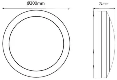
- Input: 220V-240V AC, 50Hz
- Protection: Class II (Double insulated, no earth wire required)
- Weatherproof: IP65
- Impact Rating: IK10
- Dimming: Non-dimmable
- Housing Material: Polycarbonate UV Stable
Positioning
For optimal sensor performance, follow these guidelines:
- Mount at a height of 1.8 to 2.5 meters.
- Avoid pointing at or positioning close to heat sources (heaters, extraction units) to prevent false triggering.
- Avoid pointing at bright lights.
- Avoid mounting near strong electromagnetic disturbances (e.g., electrical motors, fluorescent lamp ballasts).
Installation
- Ensure mains supply is switched off.
- Unpack the fixture and place it on a flat surface.
- Remove the front screw cover by rotating it anti-clockwise.
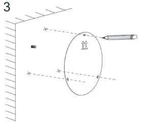
- Use the product as a template to mark 3 holes on the mounting surface, ensuring the double arrows on the rear are pointing up.
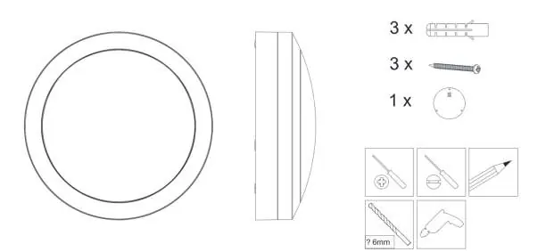
- Drill the holes and insert the supplied Rawl plugs.
- Remove the terminal block cover, loosen the cable anchor, and insert the 240V cable through the grommet.
- Connect the wires to the terminal block (L=Live, N=Neutral). Note: Earth wire is not required.
- Secure the cable anchor and terminal block cover, ensuring the weather seal is fitted neatly to maintain the IP65 rating.
- Secure the product to the wall using the 3 supplied vandal-proof screws, ensuring the arrows point up.
- Replace the front screw cover and turn clockwise to secure. Apply a small bead of silicon around the base and wall join to maintain the IP rating.
- Turn on the mains power.
Warranty
Brilliant Lighting warrants this product against defects in manufacture and workmanship for a period of 3 years from the date of purchase (3 months for non-domestic or commercial applications). Proof of purchase and proof of installation by a qualified person may be required.
Practical help
Common problems
Sensor false triggering
Ensure the sensor is not pointed at or positioned close to heat sources like heaters or extraction units.
Sensor not functioning
Avoid pointing at bright lights or mounting near strong electromagnetic disturbances like electrical motors.
Before use
- Ensure mains power is switched off before starting installation.
- Verify that the installation height is between 1.8 and 2.5 meters.
- Check that the mounting surface is flat and does not vibrate.
- Ensure you have a qualified electrician for the wiring process.
- Confirm the product is not being installed on the ceiling if IP rating maintenance is critical (wall installation recommended).
Images and diagrams
- The manual provides a template diagram showing the 3-hole mounting pattern with upward-pointing arrows.
- Wiring diagram illustrates the connection of Live (L) and Neutral (N) wires to the terminal block.
Model compatibility
- Suitable for both indoor and outdoor use.
- Not dimmable.

Manual page author
David Miller
Documentation analyst
Organizes user manual content into clear summaries, with attention to model details, product context, and everyday usability.