Home Appliances / Coffee Equipment
Service & Repair Manual for BUNN 1SH & 2SH Stand
Comprehensive service and repair guide for the BUNN 1SH and 2SH stands. Includes troubleshooting steps, component replacement procedures for circuit breakers, receptacles, rectifiers, and transformers, along with detailed wiring diagrams.
Quick answers from the manual
Quick answer
- This manual provides service and repair procedures for BUNN 1SH and 2SH stands, including component testing and replacement instructions for circuit breakers, receptacles, rectifiers, and transformers. p. 1, 5
Key actions
- Test Circuit Breaker p. 6
- Test Rectifier p. 7
- Test Transformer p. 8
Problems and fixes
Server will not heat
Check power, reset circuit breaker, inspect receptacle contacts, test transformer, or test rectifier.
p. 4Technical specifications
| Parameter | Value | Meaning | Pages |
|---|---|---|---|
| Transformer Output | 24V AC | Voltage across terminals #7 and #12 | p. 8 |
| Rectifier Output | 24V DC | Voltage across (+) and (-) terminals | p. 7 |
Where to find it in the PDF
- Troubleshooting p. 4
- Component Access p. 5
- Wiring Diagrams p. 10, 11
Table of contents
Manual images
Click an image to enlargeImportant Information
This manual is intended for qualified service personnel only. It provides detailed procedures for testing and replacing components in BUNN 1SH and 2SH stands. Always disconnect the power source before removing panels or replacing components, unless specific electrical tests require the unit to be powered. Exercise extreme caution when servicing electrical equipment and ensure all protective shields are replaced after service.
Troubleshooting
If the server will not heat, check the following:
- No power or incorrect voltage: Ensure the stand is connected to the power source.
- Circuit breaker: Check and reset if necessary. Refer to the Circuit Breaker service section for test procedures.
- Receptacle contact: Clean or replace the spring contacts.
- Transformer: Refer to the Transformer service section for test procedures.
- Rectifier: Refer to the Rectifier service section for test procedures.
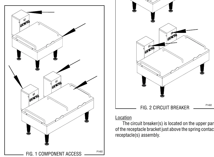
Component Access
All components are accessible by removing the receptacle cover and the stand cover. Both covers are attached with four #6-32 truss head locking screws. Ensure the stand is unplugged before removing any panels.
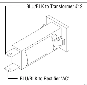
Circuit Breaker Service
The circuit breaker is located on the upper part of the receptacle bracket, just above the spring contact receptacle assembly. To test, disconnect power, remove wires, and check for continuity between terminals. If continuity is not present, press the reset button and re-test. If still no continuity, replace the breaker.
Receptacle (Spring Contacts) Service
The receptacle assembly is located on the lower front of the receptacle bracket. To replace, disconnect power, remove wires, and unscrew the two #6-32 flat head screws securing the receptacle. Install the new receptacle and reconnect wires according to the terminal diagram.
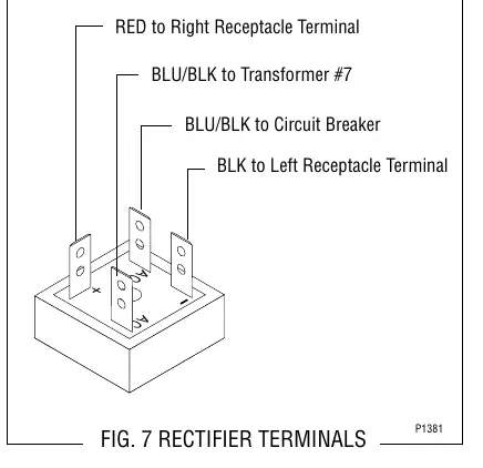
Rectifier Service
The rectifier is located inside the stand housing on the right side (for 1SH) or right and left sides (for 2SH). To test, disconnect power, remove wires, and check voltage across the (+) and (-) terminals with a voltmeter while the unit is powered. The indication must be 24 volts dc.
Transformer Service
The transformer is located in the stand housing on the base plate. To test input voltage, disconnect power, remove wires from terminals #5 and #6, and measure voltage across the black and white/red wires. The indication should be 100V, 120V, or 200-240V depending on the model. To test output, measure across terminals #7 and #12; the indication must be 24 volts ac.
Manufacturer information
Bunn-O-Matic Corporation
Practical help
Common problems
Server will not heat
Check power connection, reset circuit breaker, clean or replace receptacle contacts, test transformer, or test rectifier.
Before use
- Ensure qualified service personnel perform all inspections and repairs.
- Disconnect power source before removing panels or replacing components.
- Use a voltmeter for electrical testing.
- Replace all protective shields after servicing.
Specs in practice
- Transformer Output
- 24 volts ac (measured between terminals #7 and #12).
- Rectifier Output
- 24 volts dc (measured across + and - terminals).
Images and diagrams
- Wiring diagrams show connections for 1SH and 2SH models, including 100V, 120V, and 230V configurations.
Model compatibility
- Manual covers both 1SH and 2SH stand models.
- Wiring diagrams vary by voltage (100V, 120V, 230V).

Manual page author
Michael Turner
Technical manual editor
Reviews PDF manuals for structure, safety notes, and practical product details so readers can find the right information quickly.