Electronics / Speakers & Soundbars
User Manual for Caliber BC 112SA-PRO Active Subwoofer
Quick start guide and installation manual for the Caliber BC 112SA-PRO active subwoofer. Includes wiring diagrams, technical specifications, and safety instructions.
Table of contents
Manual images
Click an image to enlargeQuick guide from the manual
This document provides essential installation and setup instructions for the Caliber BC 112SA-PRO active subwoofer. Key requirements include ensuring at least 5cm of ventilation space around the enclosure, using a power cable of at least 15mm², and installing a fuse within 30cm of the battery. Always disconnect the battery ground before starting any electrical work.

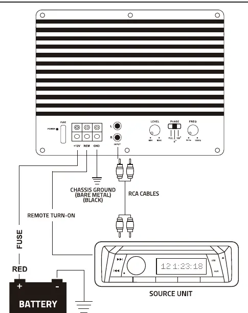
Installation
Proper installation is critical for performance and safety. Follow these steps:
- Mounting: Place the unit on a flat surface. Ensure at least 5cm of ventilation space on all sides to allow heat dissipation. Protect the unit from moisture and direct sunlight.
- Power Connection (+12V): Connect the +12V terminal directly to the vehicle battery. Use a cable of at least 15mm². Do not connect to the car fuse box.
- Fuse: Install a fuse or circuit breaker within 30cm of the battery. The fuse rating should not exceed the amplifier's internal fuse rating.
- Ground Connection (GND): Connect the ground terminal securely to the vehicle chassis. Use a cable of the same gauge as the power cable. Ensure the connection point is free of paint, undercoating, or insulation.
- Remote Turn-on (REM): Connect the REM terminal to the remote output of your head unit. If no such output exists, install a separate switch to control the amplifier's power.
Amplifier Adjustments
To achieve optimal sound quality, follow these adjustment steps:
- Set the input level adjustment knob (LEVEL) to the minimum position.
- Set the radio volume to approximately 3/4 of the maximum.
- Slowly increase the input level on the amplifier while listening for distortion. Stop increasing the level just before the sound begins to distort.
RCA Input
Connect the RCA outputs from your radio to the RCA input terminals on the amplifier. Ensure the Right output is connected to the Right input and the Left output to the Left input.
Technical Specifications
Subwoofer: 12 inch, 200W RMS / 1000W MAX power, 4 Ohm impedance, 2 inch voice coil.
Amplifier: Frequency response 25 Hz - 3.8 kHz, Low pass filter 50 - 180 Hz, S/N Ratio 92 dB, Input sensitivity 0.2 - 3 V, Phase shift 0 - 180 degrees, Sub Sonic fuse 25 A (ATO).
Enclosure: MDF construction with metal protection bars and bass reflex design.
Safety and Maintenance
If a problem occurs, stop using the device immediately to prevent injury or damage. Do not attempt to repair the unit yourself; return it to an authorized Caliber dealer. Clean the product periodically using a soft, dry cloth. For stubborn stains, dampen the cloth with water only. Ensure the operating temperature remains between 0°C and +45°C.
Manufacturer information
Caliber Europe
Practical help
Common problems
Sound distortion
Reduce the input level (LEVEL) knob. Caliber amplifiers clip softly, so adjust carefully until distortion disappears.
Amplifier does not turn on
Check the REM connection to the head unit, verify the ground connection, and ensure the main power fuse is intact.
Before use
- Ensure 5cm ventilation space around the enclosure.
- Disconnect battery ground before starting electrical work.
- Use at least 15mm² power cable.
- Install a fuse or circuit breaker within 30cm of the battery.
- Ensure RCA cables are connected correctly (Left/Right matching).
Specs in practice
- Power rating
- 200W RMS / 1000W MAX power handling capability.
- Low pass filter
- Adjustable range (50-180 Hz) to filter out high frequencies.
- Input sensitivity
- 0.2 - 3 V range to match the signal output of your head unit.
Images and diagrams
- Wiring diagram shows +12V connection to battery with fuse, REM connection to source unit, and Ground connection to chassis.
- Frequency response graphs illustrate the effect of the Low Pass Filter and Phase settings.
Model compatibility
- Requires 12V vehicle electrical system.
- Compatible with head units featuring RCA outputs.

Manual page author
David Miller
Documentation analyst
Organizes user manual content into clear summaries, with attention to model details, product context, and everyday usability.