HVAC / Parts & Accessories
Installation Guide for Carrier 30MP-900---004 Condenser Flow Switch Accessory
Quick installation guide for the Carrier 30MP-900---004 condenser flow switch. Includes mounting instructions, wiring diagrams, and LED status indicators for 30MPW017-080 chillers.
Table of contents
Manual images
Click an image to enlargeQuick Guide from the Manual
This document provides installation instructions for the Carrier 30MP-900---004 condenser flow switch, designed for use with 30MPW017-080 liquid-cooled chillers. The switch is a thermal dispersion type with a normally open contact that closes when velocity exceeds 0.66 fps (20 cm/s). Ensure all power is disconnected before starting installation.
Description
The accessory package includes the thermal dispersion flow switch and cable. It is intended for monitoring condenser water flow. Note that this accessory is not recommended for applications with variable condenser water flow for head pressure control, as it may cause nuisance alarms.
Installation
Step 1: Disconnect PowerOpen and tag all electrical disconnects to ensure the unit is powered off.
Step 2: Isolate Condenser FluidClose inlet and outlet isolation valves. Relieve residual pressure and drain the section if necessary.
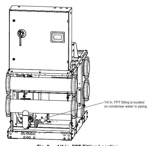
Step 3: Mount Flow SwitchFor units with manifold piping, the fitting is factory-installed. For units without, install the switch in a location with minimal shock, turbulence, and vibration. The ambient temperature must be below 160°F (71°C).
- Horizontal piping: Mount from the side if possible.
- Bottom of pipe: Ensure the area is free from deposits.
- Top of pipe: Ensure the pipe is completely filled with the medium.
- Vertical piping: Mount where the medium flows upwards.
- Turbulence: Maintain at least 10 pipe diameters from sources of turbulence (valves, elbows, etc.) upstream and 6 pipe diameters downstream.
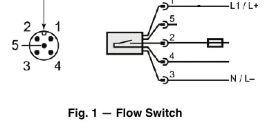
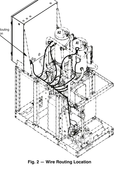
Step 4: Connect WiresRoute wires through the cable gland in the back of the control box. Connect the cable to the flow switch, noting the orientation tab. Connect switch wires (pins 2 and 4, WHT and BLK) to TB5-1 and 2. Connect 24V power (pins 1 and 3, BLU and BRN) to the panel marked CNFS.
Step 5 & 6: FinalizeOpen isolation valves, fill the condenser loop, check for leaks, and restore power.
LED Status Indicators
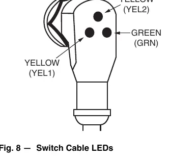
The flow sensor cable features three LEDs to indicate status:
- Green (GRN): Indicates 24V power is present.
- Yellow (YEL1): Indicates 24V power applied to the line side of the switch closure.
- Yellow (YEL2): Indicates flow is established and the switch is closed.
Both the Green and YEL1 LEDs must be ON for the switch to be operating properly.
Safety
Installation should only be performed by trained, qualified installers. Always wear safety glasses and work gloves. Observe all safety codes and be aware of potential hazards such as system pressures and electrical components.
Manufacturer information
Carrier Global Corporation
Practical help
Common problems
Nuisance water flow switch alarms
Occurs if flow is restricted to increase head pressure; accessory is not recommended for variable condenser water flow applications.
Fluid velocity too low
If velocity is less than the factory trip-point, contact your local Carrier representative for the adjustment tool and procedure.
Leaks at switch
Check for leaks after installation and ensure all air is bled from the system.
Before use
- Ensure all electrical power is disconnected and tagged.
- Isolate condenser fluid (inlet and outlet) and drain the section if necessary.
- Verify required field-supplied items: two 1/2 in. electrical connectors, varnish cloth, and potentially 1/4 in. FPT fitting.
- Ensure ambient temperature is below 160°F (71°C).
- Check for damage to the parts upon receipt.
Specs in practice
- Compatibility
- Designed for 30MPW017-080 liquid-cooled chillers.
Images and diagrams
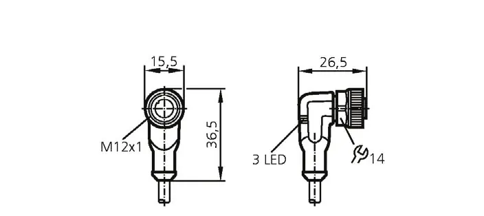
- Fig 1: Flow switch dimensions and orientation tab.
- Fig 2: Wire routing location in the control box.
- Fig 8: LED status indicators (Green for power, Yellow for switch closure).
Model compatibility
- Not recommended for units with variable condenser water flow for head pressure control.

Manual page author
David Miller
Documentation analyst
Organizes user manual content into clear summaries, with attention to model details, product context, and everyday usability.