HVAC / Air Conditioners
Installation Guide for Carrier 17EX Centrifugal Liquid Chiller
Comprehensive installation guide for the Carrier 17EX Centrifugal Liquid Chiller. Includes safety precautions, rigging instructions, piping and electrical connection procedures, insulation guidelines, and start-up checklists.
Quick answers from the manual
Quick answer
- The 17EX is a centrifugal liquid chiller. Installation involves receiving and inspecting the unit, rigging it into place, installing supports, connecting water piping to heat exchangers and oil coolers, making electrical connections, and applying field insulation. p. 2, 12, 18, 26
Key actions
- Rigging the chiller p. 5, 6
- Connecting water piping p. 13, 15
- Making electrical connections p. 18, 19
Problems and fixes
Chiller vibration
Ensure the chiller is properly leveled within 1/16-in. with respect to each other using support plates and leveling pads.
p. 12Technical specifications
| Parameter | Value | Meaning | Pages |
|---|---|---|---|
| Refrigerant | HCFC-134a | Refrigerant type used in the chiller. | p. 9 |
Where to find it in the PDF
- Safety Considerations p. 1
- Rigging Guide p. 5
- Typical Field Wiring p. 20
Table of contents
Manual images
Click an image to enlargeQuick Guide from the Manual
This guide provides essential installation instructions for the Carrier 17EX Centrifugal Liquid Chiller. Key procedures include proper rigging, establishing water and electrical services, and applying field insulation. Always refer to the full PDF for specific job-site wiring diagrams and certified drawings.
Safety Considerations
DANGER: Refrigerant vapor is harmful and can cause asphyxiation hazard. Do not vent refrigerant relief devices indoors. Ensure adequate ventilation per ASHRAE 15.
- Do not use oxygen to purge lines or leak test.
- Do not weld or flame cut refrigerant lines until all refrigerant is removed.
- Ensure all power is off and residual voltage is discharged before working on electrical components.
- Use mechanical equipment (crane, hoist) to lift heavy components.
- Do not step on refrigerant lines.
Receiving and Rigging
Upon receipt, inspect the chiller for shipping damage while still on the conveyance. Do not open valves or loosen connections until ready for installation. The chiller may be shipped with a nitrogen holding charge or isolated refrigerant charge.
Rigging the Chiller
- The 17EX can be rigged as an entire assembly or separated into components (compressor, economizer, motor, gear, cooler, condenser).
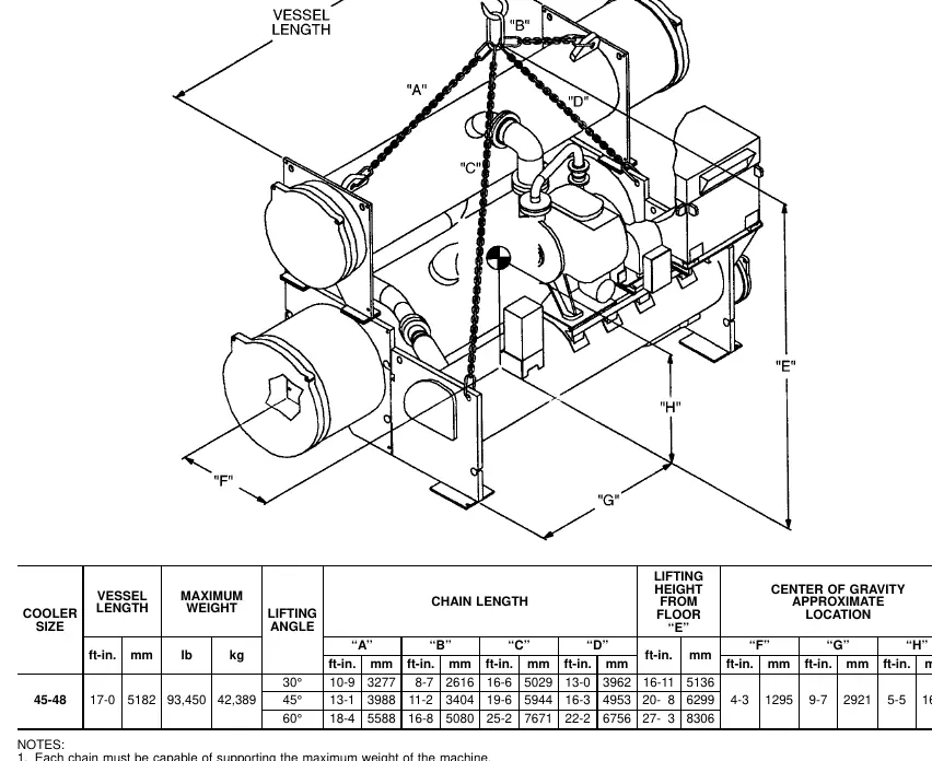
- Lift the chiller only from the 4 points indicated in the rigging guide (Fig. 3).
- Each lifting cable or chain must be capable of supporting the entire weight of the chiller.
- When rigging components separately, the open drive motor and gear must be removed to avoid overturning.
Installation
Chiller Supports
The chiller must be level within 1/16-in. Use support plates and shear flex pads for standard isolation. For uneven floors, use soleplates and leveling pads with non-shrinking grout.
Connecting Piping
- Water Piping: Install piping using job data and piping drawings. Ensure water flow direction is as specified in Fig. 9. Entering water is always the lower nozzle; leaving water is the upper nozzle.
- Oil Coolers: Connect water to the compressor and external gear oil coolers. Water supply may be city water or chilled water.
- Relief Venting: Vent relief devices outdoors in accordance with ASHRAE 15.
Electrical Connections
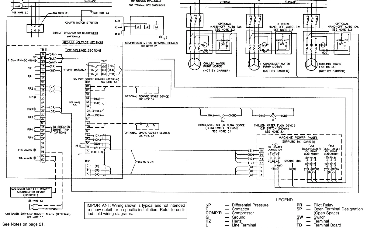
Field wiring must comply with job wiring diagrams and applicable electrical codes.
- Control Inputs: Connect chilled and condenser water flow switches to the starter terminal strip.
- Control Outputs: Connect auxiliary equipment, pumps, and alarms as required.
- Motor Terminals: Insulate compressor motor terminals and lead wire ends to prevent moisture condensation and arcing.
- CCN Interface: The Carrier Comfort Network (CCN) communication bus uses shielded, 3-conductor cable in a daisy chain arrangement.
Insulation
Insulate the following components at the job site: cooler shell, cooler tube sheets, suction piping, oil reclaim tube, cooler liquid supply piping, hot gas bypass, economizer/storage vessel shell, end plate, low-side float chamber, and compressor vent line to cooler. Protect insulation from weld heat damage during installation.
Start-up Checklist
Before requesting start-up, ensure the following:
- Chiller is level.
- All piping is installed and supported with correct flow direction.
- Relief valves are piped to the atmosphere.
- Electrical wiring is complete and checked.
- Chilled and condenser water lines are filled, tested, flushed, and vented.
Manufacturer information
Carrier Global Corporation
Practical help
Common problems
Chiller vibration
Ensure the chiller is properly leveled within 1/16-in. with respect to each other using support plates and leveling pads.
Oil cooler damage
Ensure water used for oil cooling is clean and noncorrosive. Use proper flow rates as specified in the manual.
Relief valve chattering
Ensure the 3-way dual shutoff valve is either fully front seated or back seated; do not leave it in the center position.
Before use
- Inspect shipment for damage before removal from conveyance.
- Verify chiller model and serial number against shipping papers.
- Ensure all lifting equipment is rated for the chiller weight.
- Confirm all electrical circuits are de-energized and locked out before servicing.
- Verify water flow direction as specified in Fig. 9.
Specs in practice
- Nominal Tons
- Capacity range of the chiller (1500 to 2250 tons).
- Design Maximum Water Pressure
- Maximum pressure the waterbox is rated to withstand (150 or 300 psig).
Images and diagrams
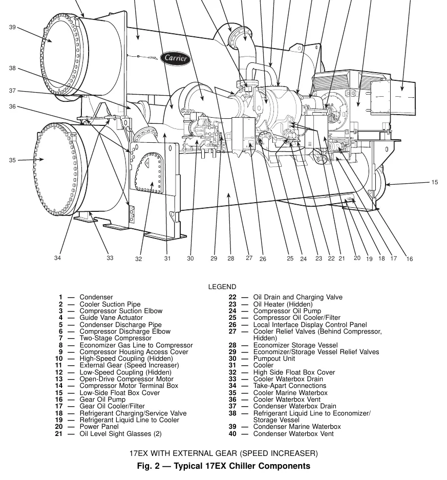
- Fig. 2 shows the main components of the 17EX chiller.
- Fig. 3 provides the rigging guide with lifting points and chain lengths.
- Fig. 9 details the nozzle arrangements for different waterbox types.
- Fig. 15 and 16 provide typical field and control wiring diagrams.
Model compatibility
- Chiller is designed for use with HCFC-134a refrigerant.
- Waterbox insulation must be field supplied.
- Relief valve discharge pipe sizing must be calculated per ASHRAE 15.

Manual page author
Emily Carter
User documentation editor
Prepares concise manual descriptions and highlights the most useful setup, operation, and maintenance information for readers.