Industrial / Access Control
Installation Guide for Carrier 14ASI Remote Evaporator
Comprehensive installation guide for the Carrier 14ASI remote evaporator accessory. Includes safety protocols for R-32 refrigerant, mounting instructions, wiring diagrams, and refrigerant charging procedures.
Table of contents
Manual images
Click an image to enlargeQuick Guide from the Manual
This document provides installation instructions for the Carrier 14ASI remote evaporator mounting accessory used with 30RC units. The system utilizes A2L (R-32) refrigerant, which requires specific safety precautions, including proper ventilation, leak detection, and handling procedures. Only trained, qualified installers should perform these operations.
Safety Considerations
Installation involves system pressures, electrical components, and elevated locations. Observe the following:
- A2L Refrigerant (R-32): This refrigerant is flammable. Do not use a torch to remove components.
- Leak Detection: A leak detector compliant with UL 60335-2-40 Annex LL is required, set to trip at 25% of the Lower Flammability Limit (LFL).
- Ventilation: Ensure adequate ventilation in enclosed or low-overhead areas to prevent refrigerant accumulation.
- Electrical Safety: Shut off all power and tag disconnect locations before starting work.
Installation Overview
The installation process involves relocating the evaporator to an indoor space. Key steps include:
- Inspect package contents and verify the new location can support the evaporator weight.
- Turn off electrical power and perform lockout/tag-out procedures.
- Recover refrigerant charge from all circuits before cutting lines.
- Disconnect existing thermistors, water piping, flow switch cables, and EXV cables.
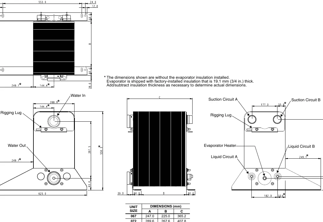
- Transport the evaporator to the new location and secure it vertically.
- Reinstall the filter drier, EXV, and service valve assembly.
- Install field-supplied liquid and suction lines, ensuring proper sizing.
- Install pressure relief valves on new liquid lines.
- Perform leak testing and dehydration vacuum procedures.
- Reconnect electrical components, including thermistors and EXV cables, using the provided junction box and extension cables.
Piping and Connections
Follow these guidelines for piping:
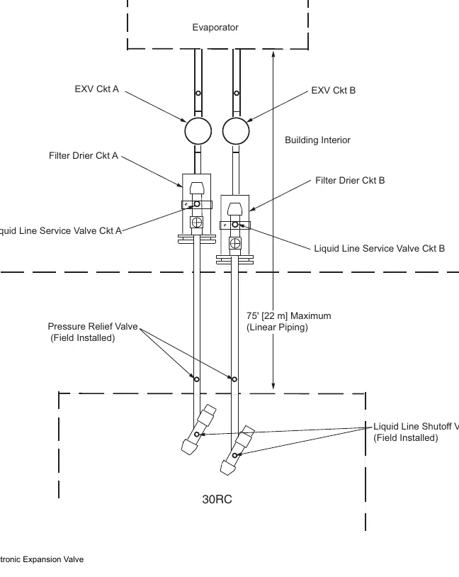
- Maximum Separation: 75 linear ft (22 m) for plate fin coils; 50 linear ft (15 m) for microchannel coils.
- Elevation: Maximum evaporator elevation above the condensing section is 15 ft (4.5 m).
- Insulation: Minimum R-value of 25 (m deg. K/W) is recommended for suction and water lines.
- Brazing: Use a nitrogen purge while brazing. Remove pressure transducers, Schrader cores, thermistors, and fusible plugs before brazing to avoid damage.
Refrigerant Charging
The system requires additional refrigerant based on the separation distance and line sizes. Refer to the following:
- Charging: Charge at the liquid line. Do not charge into the suction line.
- Calculations: Use Table 4 for estimated additional charge per 100 ft of tubing. Apply temperature correction factors from Table 5 if necessary.
- Verification: Use the nameplate charge amount or Table 6 for initial charging. Adjust based on actual operating conditions.
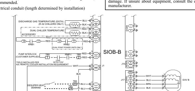
Wiring and Electrical
A normally open relay must be wired between TB5-1 and TB5-2 to shut down the chiller if a leak is detected. Use the provided 5-wire jacketed cable to connect thermistor leads in the junction box back to the base unit control box. Ensure all splices are soldered and insulated to prevent short circuits.
Manufacturer information
Carrier Global Corporation
Practical help
Common problems
Chiller alarms 'CUSTOMER INTERLOCK FAILURE'
Ensure the normally open relay is correctly wired between TB5-1 and TB5-2. This connection is required for the leak detection system.
Oil level remains low after charging
Check the piping system for proper design for oil return and verify suction line sizing. If oil does not return to acceptable sight glass levels, add oil as specified.
Excessive pressure drop (5-8 psi) after 24 hours
Replace the filter drier or filter drier core.
Before use
- Verify the new location can support the evaporator weight.
- Ensure all safety codes for A2L (R-32) refrigerant are followed.
- Have nitrogen purge equipment ready for brazing.
- Confirm availability of proper refrigerant recovery cylinders.
- Check that all necessary field-supplied materials (piping, insulation, conduit) are on hand.
Specs in practice
- Maximum separation
- 75 ft (22 m) for plate fin coils; 50 ft (15 m) for microchannel coils.
- Maximum elevation
- 15 ft (4.5 m) above the condensing section.
- Insulation R-value
- Minimum 25 (m deg. K/W) recommended for suction and water lines.
Images and diagrams
- Fig 1: Wiring for chiller shut down during leak detection.
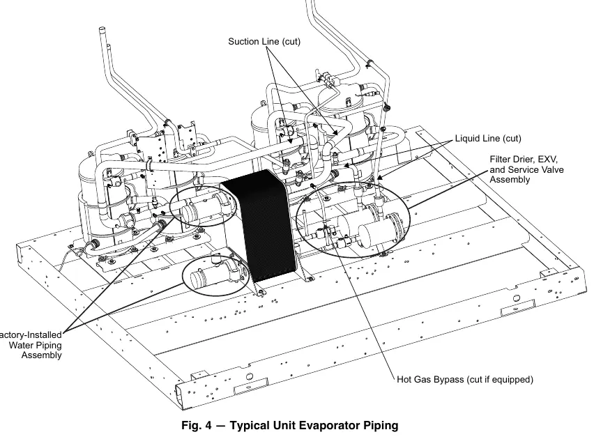
- Fig 4: Typical unit evaporator piping layout.
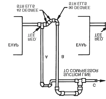
- Fig 7: Double suction riser configuration.
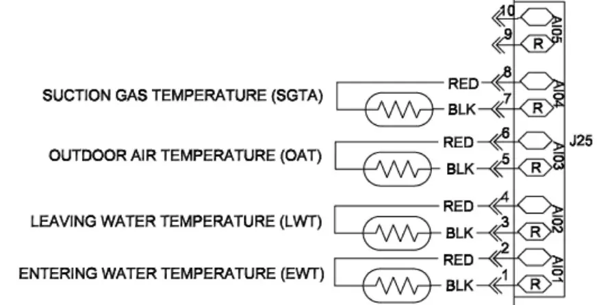
- Fig 8: SIOB-A-J25 connector wiring.
Model compatibility
- Compatible with 30RC units using R-32 refrigerant.
- Not for use with other refrigerants.

Manual page author
Emily Carter
User documentation editor
Prepares concise manual descriptions and highlights the most useful setup, operation, and maintenance information for readers.