HVAC / Air Conditioners
Installation, Start-Up, and Service Manual for Carrier 09XC Remote Air-Cooled Condenser Units
Comprehensive installation, start-up, and service guide for Carrier 09XC remote air-cooled condenser units. Includes mounting instructions, refrigerant piping, electrical wiring, VFD configuration, and maintenance procedures.
Table of contents
Manual images
Click an image to enlargeQuick Guide from the Manual
This document provides essential instructions for the installation, start-up, and maintenance of Carrier 09XC remote air-cooled condenser units. These units are designed for indoor mounting in high-rise buildings and are intended for use with 50XCR vertical packaged units. Only trained, qualified personnel should perform installation and service.
Safety Considerations
Installation and service can be dangerous. Always shut off all power to the equipment before beginning work. Use care when handling, rigging, and setting bulky equipment. Do not use a torch to remove components as the system contains oil and refrigerant under pressure.
Installation
Rigging and Placing the Unit
Units are mounted on skids. Use a minimum of 3 rollers when rolling the unit into position. Ensure the location is not adjacent to acoustically sensitive spaces. Maintain a minimum of 6 ft of clearance between condenser air openings for units on the same floor, and 10 ft for floor-to-floor installations.
Refrigerant Piping
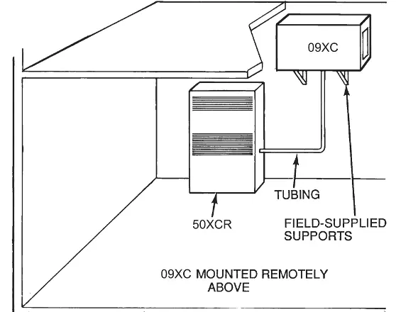
All field leak and pressure testing must comply with local codes or ASHRAE Standard 15. Use a mini tubing cutter for parts removal and perform phos-copper brazing. A refrigerant receiver is not recommended. If the condenser is installed above the evaporator, a field-supplied check valve is recommended on the hot gas discharge line.
Ductwork
The unit can be used with or without ductwork. If used, ensure ducts are as short as possible and insulated to prevent moisture condensation. Single deflection discharge louvers can be applied to minimize air recirculation.
Electrical Connections
Verify that nameplate electrical requirements match the power supply. Ensure phase imbalance is less than 2%. Power wiring must include adequate overcurrent protection (fuses or HACR breakers). Connect 24-v control wires to the compressor contactor.
Start-Up
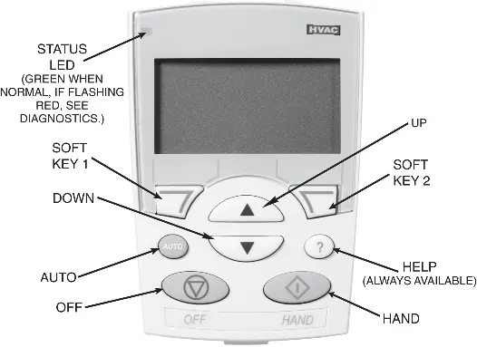
Complete the Start-Up Checklist before attempting system start-up. The unit may feature a factory-installed refrigerant pressure-controlled VFD (variable frequency drive) for low ambient operation. If installing a low ambient kit in the field, ensure the VFD parameters are configured according to the tables provided in the manual.

Service and Maintenance
Cleaning
Clean condenser coils with a vacuum cleaner, fresh water, compressed air, or a bristle brush. Steam cleaning is not recommended. Keep drains free of dirt and trash.
Fan Adjustment
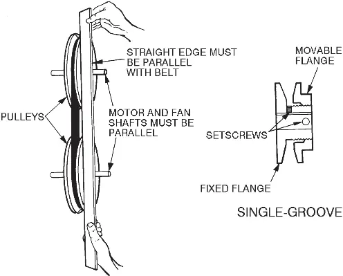
Units are belt-driven. To change fan speed, shut off power, loosen the fan belt, and adjust the movable pulley flange. Ensure proper pulley alignment and belt tension (approximately 1/2 in. deflection with 8-lb tension) after adjustment.
Troubleshooting
Refer to the troubleshooting table for common issues such as unit failure to start, fan operation problems, compressor noise, or unit vibration. Always check power sources, fuses, and electrical contacts first.
Manufacturer information
Carrier Global Corporation
Practical help
Common problems
Unit will not start
Check power source, fuses, circuit breakers, disconnect switch, and electrical contacts.
Fan does not operate
Check contactor or relay, test motor, replace broken belt, or tighten loose electrical contacts.
Compressor is noisy but will start
Check for under voltage, missing phase, or seized compressor. Replace compressor if defective.
Unit is noisy
Check for internal noise, tube vibration, or loose panels/parts.
Before use
- Verify all shipping materials have been removed.
- Check for shipping damage.
- Verify power supply matches unit nameplate.
- Ensure ground wire is connected.
- Verify circuit protection is sized and installed properly.
- Check fan rotation.
- Ensure air filters are in place and clean.
Specs in practice
- Nominal Capacity
- Cooling capacity measured in tons.
Images and diagrams
- Fig 1: Base unit dimensions for 09XC06-24.
- Fig 2: Mounting applications including remote suspension.
- Fig 3: Rigging details for moving the unit.
- Fig 7: Fan pulley adjustments and alignment.
- Fig 11/12: Wiring schematics for low ambient options.
Model compatibility
- Designed for use with 50XCR vertical packaged units.
- VFD parameters must be configured based on the specific motor nameplate FLA.

Manual page author
David Miller
Documentation analyst
Organizes user manual content into clear summaries, with attention to model details, product context, and everyday usability.