Industrial / Hydraulic Presses
User Manual for Dake Force 10DA and Force 25DA Hydraulic Press
Quick guide for the Dake Force 10DA and Force 25DA hydraulic press. Includes installation, wiring, operation, lubrication, troubleshooting, and parts diagrams.
Table of contents
Manual images
Click an image to enlargeQuick Guide
This manual provides instructions for the Dake Force 10DA and 25DA hydraulic presses. Key operations include proper assembly of the pumping unit, correct wiring for 110V or 220V power, and routine maintenance such as lubrication and oil changes. Always ensure all bolts and fittings are tight before operation. This machine is intended for one-person operation and is not designed for stripping operations.
Installation Instructions
The press may require some assembly upon arrival. Keep the press frame mounted on the shipping skid for ease of assembly.
- Remove plastic from the machine.
- With the press laying on its side, locate the four holes on the side facing up.
- Place the pumping unit on the side of the press with the mounting bracket facing down, ensuring the holes align.
- Secure the pumping unit using the four bolts, washers, and nuts provided in the accessory box. Ensure all are tight.
- Fill the reservoir with 3 gallons of Mobil DTE 24 hydraulic fluid or equivalent AW 32.
Wiring Instructions
Warning: A licensed qualified electrician must wire and install the electrics on this machine.
The machine is shipped as a 110V unit. To convert to 220V single phase:
- Change the leads on the motor to fit 220 volts, following the diagram provided on the motor cover.
- Install a plug and wire rated for the voltage and amperage listed on the motor.
Operation
- Fill the reservoir with 3 gallons of Mobil DTE 24 hydraulic fluid or equivalent AW 32.
- Turn the on/off toggle switch to the "on" (up) position.
- Move the control lever down to advance the ram.
- Release the control lever to stop the ram.
- Move the control lever handle up to retract the ram.
- When the press is new, cycle the ram up and down to remove any air from the system.
Lubrication
Keep all working parts well oiled. Apply a light film of oil over the entire surface of the ram to prevent rust. Use only recommended DTE 24 hydraulic oil; do not use transmission fluid, as it will damage the seals and void the warranty.
Troubleshooting
If the ram moves in the neutral position, re-adjust the 4-way valve by centering the valve stem. If the ram runs jerky, there is likely air in the system; cycle the ram up and down approximately 15 times to bleed it. If the machine fails to build pressure, the relief valve may need resetting (do not exceed 2413 PSI). If the motor overheats, check the duty cycle or ensure no extension cord is being used.
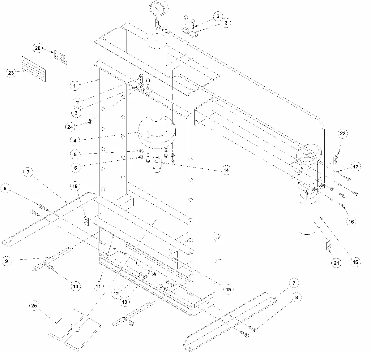
Parts List and Diagrams
The manual includes detailed parts lists and exploded view diagrams for the press frame and workhead assemblies. When ordering parts, always provide the part number, name, and the model number found on the plate attached to the press frame.
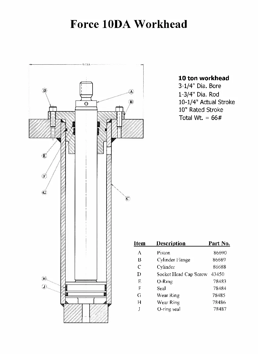
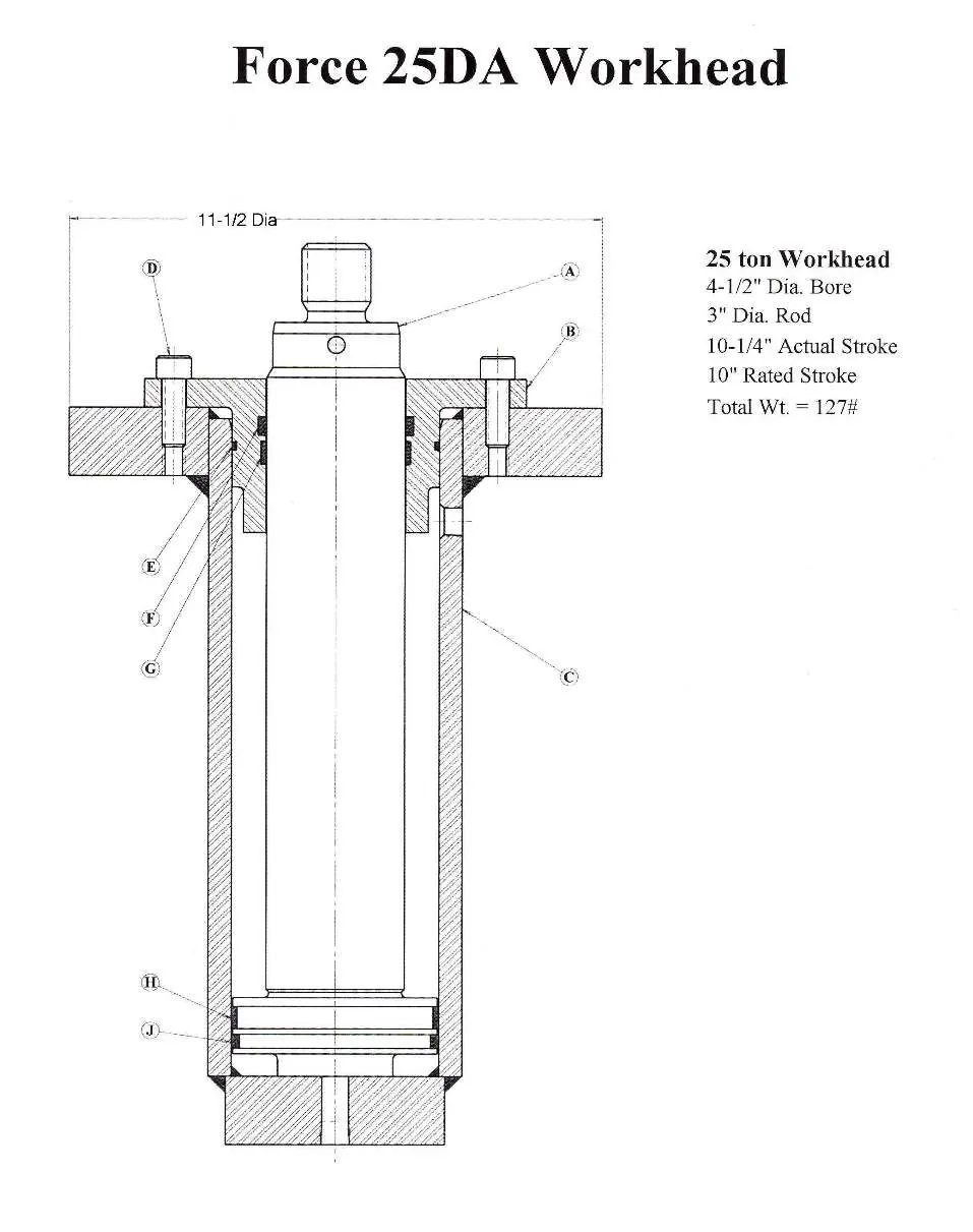
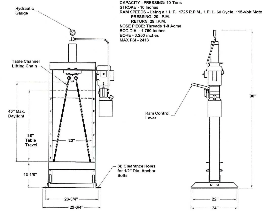
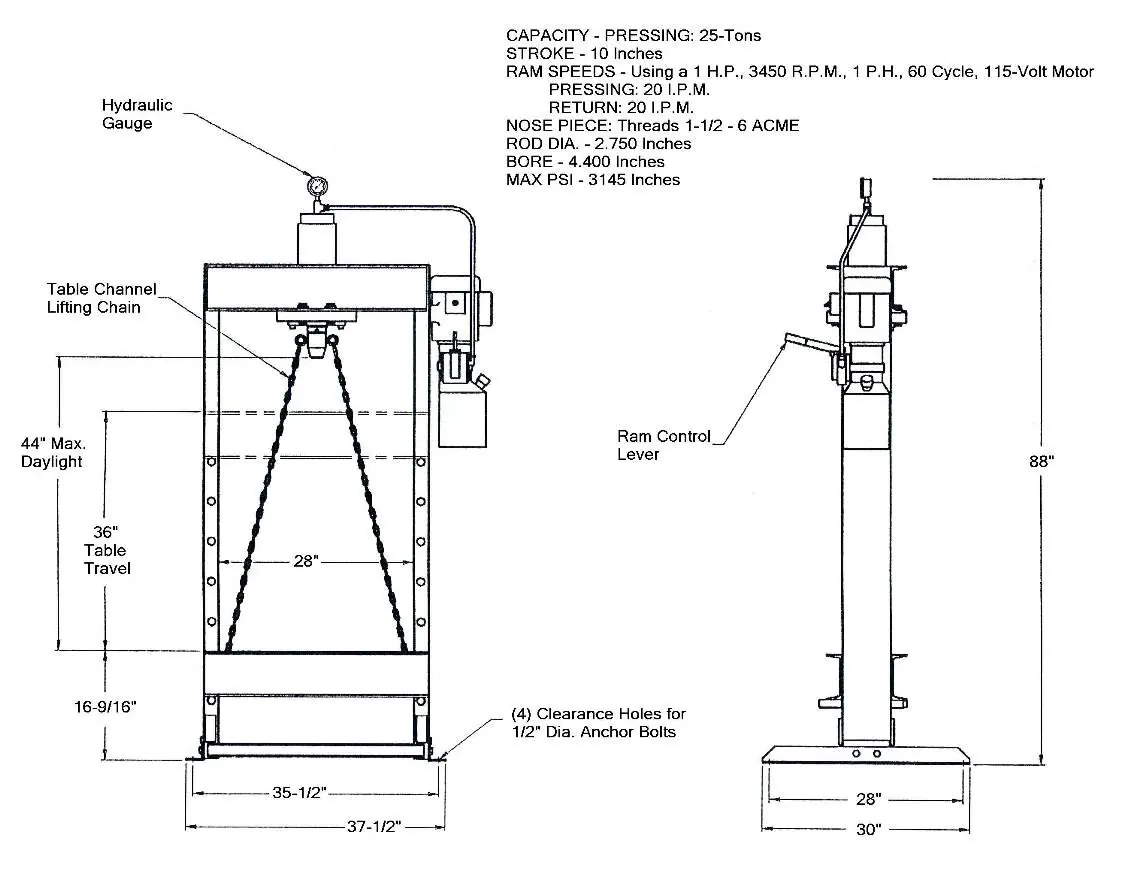
Specifications
The Force 10DA and 25DA models differ in capacity (10-Tons vs 25-Tons), bore size, and rod diameter. Refer to the specific specification pages for detailed dimensions, ram speeds, and motor requirements.
Safety
Always observe safety labels. This machine is not designed for stripping operations. Ensure all fittings and bolts are tight before operation. Contact Dake at 616-842-7110 or via email at [email protected] for support.
Manufacturer information
DAKE Corporation
Practical help
Common problems
Ram moves in neutral position
Re-adjust the 4-way valve by centering the valve stem.
Ram runs jerky
Air in the system; run ram up and down approximately 15 times to self-bleed.
Machine will not build desired pressure
Relief valve needs to be reset. Remove octagon cap from back of manifold and adjust set screw (Do not exceed 2413 PSI).
Motor overheats and shuts down
Duty cycle exceeded or extension cord is being used. Remove extension cord and check motor duty cycle.
Before use
- Ensure all bolts and fittings are tight.
- Fill reservoir with 3 gallons of Mobil DTE 24 hydraulic fluid or equivalent AW 32.
- Verify electrical wiring matches the motor voltage (110V or 220V).
- Cycle the ram up and down to remove air from the system.
- Ensure the press is operated by one person.
Images and diagrams
- Parts diagram shows the assembly of the press frame and components.
- Workhead diagrams detail the cylinder, piston, and seal components for maintenance.
Model compatibility
- Machine is shipped as 110V; can be converted to 220V single phase by a qualified electrician.
- Not intended for stripping operations.

Manual page author
David Miller
Documentation analyst
Organizes user manual content into clear summaries, with attention to model details, product context, and everyday usability.