Lighting / Controllers & Dimmers
DALI to 0-10V Converter User Manual
A comprehensive user guide for the Control Freak DALI to 0-10V Converter. This manual covers installation, wiring diagrams, DALI configuration, dimming curves, and technical specifications for the Type 5 device.
Table of contents
Manual images
Click an image to enlargeQuick guide from the manual
The DALI to 0-10V Converter is a DIN-mount controller designed to bridge DALI systems with 0-10V lighting devices. Key requirements:
- Power Supply: Requires a 24VDC (>100mA) source connected to the DC IN terminals.
- Polarity: The 0-10V connection is polarity sensitive and must be wired correctly. The DALI connection is not polarity sensitive.
- Relay Usage: An internal relay is available to disconnect power to 0-10V devices when an 'off' command is received, as some devices do not dim to zero.
Description
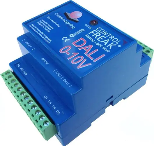
The DALI to 0-10V Converter is a DIN-mount controller that allows DALI systems to control 0-10V devices. It supports DALI broadcast, addressing, groups, and standard DALI settings. It features a 4-pole DIN mount case made of UL94V0 material and removable 12-way terminals for easy wiring.
Installation and Connection
DC Supply: Connect a 24VDC (>100mA) power source to the screw terminals marked DC IN + and -. The device is not polarity sensitive regarding the DC input. The 'DC OK' LED will illuminate when power is present.
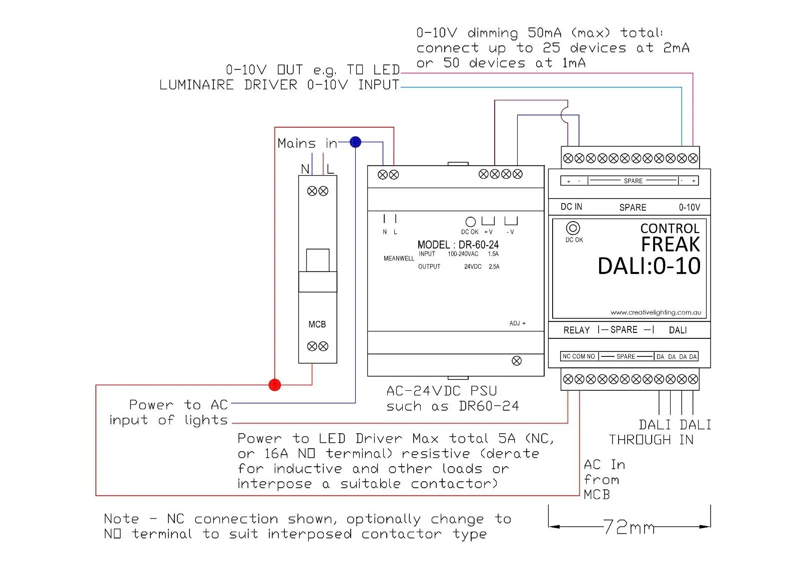
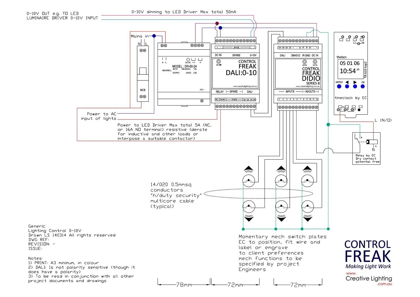

0-10V Connection: Connect the 0-10V output to the 0-10V input of your lighting devices. Note that this connection is polarity sensitive. The converter can sink or source 50mA of current, supporting between 25 to 50 devices depending on their current draw.
Relay Connection: Optionally, connect the active line to the Normally Open (NO) input on the relay and the active line running to the 0-10V devices to the Common (COM) terminal. This allows the converter to physically disconnect power to the lights when an 'off' command is received.
DALI Connection: Connect the DALI line wires to the screw terminals at the bottom right of the enclosure. DALI is not polarity sensitive. Use a minimum cable diameter of 1mm sq.
Configuration and Operation
The converter behaves as a single DALI luminaire, supporting standard DALI commands such as broadcast, addressing, groups, scenes, and fade times. It provides a linear output by default, translating DALI arc levels directly to 0-10V values.
Fade Times: The device supports configurable fade times. If a fade time of 0 is selected, the device uses 'Extended Fade Times' calculated via a specific base value and multiplier.
Dimming Curves: You can select between logarithmic or linear dimming curves using Type 5 command 229 (0 for logarithmic, 1 for linear).
Physical Minimum: The physical minimum can be set to dictate when power is cut off to the 0-10V output. In logarithmic mode, if the physical minimum is set to 10%, any arc level below 10% will trigger the relay to turn off.
Type 5 Commands
To send a Type 5 command, you must first send the 'Enable Device Type 5' command (272). The desired command must be sent within 100ms of the enable command. Supported commands include:
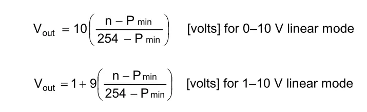
- 224: Set output range to 1-10V
- 225: Set output range to 0-10V
- 228: Store DTR as physical minimum
- 229: Select dimming curve
- 230: Reset converter settings
- 238: Query dimming curve
- 239: Query output level
- 242: Query converter status
Technical Specifications
Relay Contact Ratings:
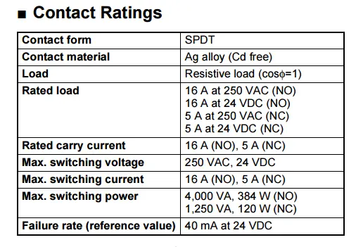
- Contact Form: SPDT
- Contact Material: Ag alloy (Cd free)
- Rated Load (NO): 16A at 250VAC or 24VDC
- Rated Load (NC): 5A at 250VAC or 24VDC
- Max Switching Power: 4,000 VA (NO), 1,250 VA (NC)
Practical help
Common problems
0-10V devices do not turn off completely.
Ensure the internal relay is wired to disconnect power to the 0-10V devices when an 'off' command is received.
Device does not power on.
Verify that a 24VDC (>100mA) power supply is connected to the DC IN terminals.
Communication or dimming issues.
Check the 0-10V wiring polarity; unlike DALI, the 0-10V connection is polarity sensitive.
Before use
- Ensure a 24VDC (>100mA) power supply is available.
- Verify DALI line cable diameter is at least 1mm sq.
- Check polarity for 0-10V connections.
- Determine if the internal relay is needed to fully disconnect power to 0-10V devices.
- Ensure the DALI line connects to a DALI power supply unit.
Images and diagrams
- The wiring diagram shows the connection of the 24VDC power supply to the DC IN terminals.
- It illustrates the connection of the 0-10V output to the LED driver.
- It demonstrates the use of the internal relay to switch the AC power to the LED driver.
Model compatibility
- Complies with DALI version 2.
- Supports DALI Type 5 commands.
- Compatible with standard DALI controllers and power supplies.

Manual page author
David Miller
Documentation analyst
Organizes user manual content into clear summaries, with attention to model details, product context, and everyday usability.