Industrial / Electrical
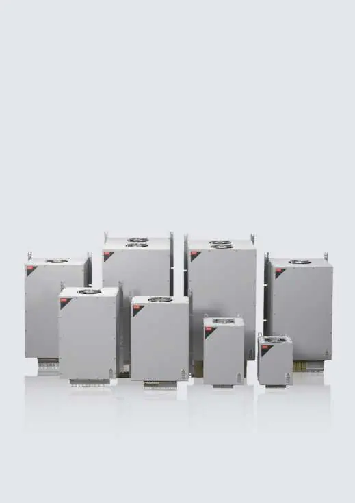
Danfoss VLT® Advanced Harmonic Filter AHF 005/AHF 010 Design Guide
Comprehensive design and installation guide for Danfoss VLT® Advanced Harmonic Filters AHF 005 and AHF 010. Includes technical specifications, mounting instructions, wiring diagrams, programming parameters, and spare parts information.
Table of contents
Quick guide from the manual
This design guide provides essential information for the installation, operation, and maintenance of the Danfoss VLT® Advanced Harmonic Filters AHF 005 and AHF 010. These filters are designed to mitigate harmonic distortion in electrical systems using VLT® frequency converters. Important: Only qualified personnel are permitted to install, commission, and maintain this equipment. Always observe safety precautions, including waiting for capacitors to discharge before performing any service.
Operating Principle
The AHF 005 and AHF 010 filters consist of a main inductor and a 2-stage absorption circuit. They are tuned to eliminate harmonics starting from the 5th harmonic. The AHF 005 provides 5% THDi performance, while the AHF 010 provides 10% THDi performance. Performance varies based on load; at part load, THDi may be higher, but the absolute harmonic current is lower.
Installation Requirements
Mechanical Mounting
- Mount filters vertically with terminals at the bottom.
- Ensure top and bottom clearances of at least 150 mm.
- Do not mount near heat-sensitive materials or other heating elements.
- Use dedicated lifting eyes for installation.
- For rail-mounted installations, use a backplate to prevent false airflow.
Electrical Installation
- Connect mains supply to terminals X1.1–X1.3.
- Connect drive supply to terminals X2.1–X2.3.
- Optional capacitor disconnect terminals are X3.1–X3.3 and X4.1–X4.3.
- Use shielded cables for control wiring to avoid high-frequency noise coupling.
Overtemperature Protection
The filters are equipped with thermal switches. If the filter overheats (above 140 °C), the switch opens. It is mandatory to use this switch to prevent damage. Program the frequency converter to perform an immediate stop or controlled ramp down within 30 seconds if the switch activates.
Programming
Parameters are available to configure digital inputs and outputs for filter operation, including overtemperature protection and capacitor disconnect control. Refer to the specific parameter groups (5-0*, 5-1*, 5-3*) for detailed settings.
Specifications
The filters are designed for various voltage classes (380–690 V) and frequencies (50/60 Hz). They feature an overload capacity of 160% for 60 seconds every 10 minutes. Detailed power loss and acoustic noise data are provided in the guide for each filter size and load percentage.
Spare Parts
Spare parts are revision-specific. Always check the revision number on the product label (characters 5 and 6 of the serial number) before ordering kits, including capacitor kits, terminal kits, fan kits, and fuse kits.
Manufacturer information
Danfoss A/S
Practical help
Common problems
Overtemperature protection activation
Evaluate airflow and installation conditions. Check if fan inlet/outlet is blocked, or if the fan or fan control is defective.
High capacitive current at no-load
Use a capacitor disconnect contactor to disconnect the capacitor bank at loads below 20%.
Voltage boost at low load
Consider using a capacitor disconnect to reduce voltage boost, especially in 690V applications where voltage tolerance is reduced.
Before use
- Verify the filter revision number on the product nameplate.
- Ensure the filter is mounted vertically with terminals at the bottom.
- Check that top and bottom clearances are at least 150 mm.
- Confirm the supply voltage matches the filter specifications.
- Ensure qualified personnel perform the installation.
- Check that the capacitor disconnect terminals are correctly wired if used.
Images and diagrams
- Connection Diagram (Figure 23): Illustrates terminal layout for mains, drive, and optional capacitor disconnect.
- Lifting Method (Figure 16/17): Shows correct lifting points for internal and external fan models.
- Airflow (Figure 18/19): Demonstrates correct airflow requirements and backplate usage.
- Temperature Derating (Figure 30): Shows the load percentage vs. ambient temperature curve.
Model compatibility
- Designed for use with VLT® HVAC Drive FC 102, Refrigeration Drive FC 103, AQUA Drive FC 202, and AutomationDrive FC 301/302.
- Not for use with third-party frequency converters.
- In 690 V applications, only filters of identical size shall be configured in parallel.

Manual page author
David Miller
Documentation analyst
Organizes user manual content into clear summaries, with attention to model details, product context, and everyday usability.