Industrial / Electrical
Installation Guide for Danfoss Ejector Controller EKE 80 (080G5022)
Comprehensive installation and configuration guide for the Danfoss EKE 80 Ejector Controller (080G5022). Includes wiring diagrams, technical specifications, I/O configuration, and safety warnings for professional installation.
Table of contents
Manual images
Jump to the sectionQuick guide from the manual
The Danfoss EKE 80 Ejector Controller (080G5022) is designed to control multiple HP/LP ejectors and up to 2 modulating control valves. It facilitates the 'lift' of MT suction pressure to decrease energy consumption. This device is suitable for both new and retrofit systems and is intended for professional use only.
Safety and installation warnings
- Qualified personnel only: All service and maintenance must be performed by qualified professionals.
- Mounting: Recommended vertical mounting position.
- Electrical safety: Always disconnect from the main power supply before working on electrical connections. Ensure the device is fitted inside an electrical panel with no live parts accessible.
- Environment: Avoid exposure to corrosive gases, high humidity (>90%), strong vibrations, or extreme temperature fluctuations.
- Wiring: Use appropriate cable ends and ensure screws are tightened securely. Separate probe/digital input cables from power cables to avoid electromagnetic noise.
Technical specifications
- Power supply: 21–265 V AC, 50/60 Hz or 40–230 V DC. Maximum power consumption: 15 W.
- Protection: IP40 (front cover only).
- Operating conditions: -20 to +60 °C (CE), 0 to 50 °C (UL).
- Communication: Supports CANbus, USB (host/device), RS485, and Ethernet.
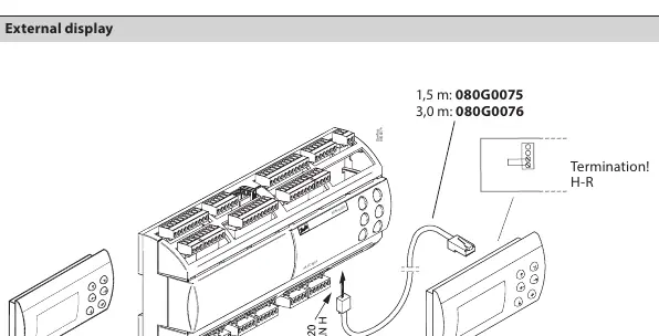
User interface and settings
The controller features an LCD display (128 x 64 dots). To adjust display settings like contrast and brightness:
- Power on the device.
- Press and release the Enter and X keys simultaneously to access the BIOS menu.
- Select the DISPLAY menu.
- Use the UP and DOWN arrow keys to adjust the desired level.
Connections and I/O
The controller features extensive I/O capabilities, including digital inputs, analog inputs, and digital outputs. Refer to the connection diagrams for specific pinouts. Note that for Multi-Ejector setups, an external Solid State Relay is required between the assigned digital output and the solenoid coils to ensure leakage current suppression.
Maintenance
Before performing any maintenance, disconnect all electrical connections. Avoid touching electronic components on the board to prevent electrostatic discharge.
Manufacturer information
Danfoss A/S
Practical help
Common problems
Display contrast or brightness is incorrect.
Access the BIOS menu by pressing Enter and X simultaneously at power-on, then navigate to the DISPLAY menu to adjust settings.
Multi-Ejector control issues.
Ensure an external Solid State Relay is installed between the digital output and the solenoid coils to handle leakage current suppression.
Communication errors.
Verify cable types and termination. Ensure RS485/CANbus wiring follows the specified wire lengths and gauge requirements.
Before use
- Verify supply voltage is within 21–265 V AC or 40–230 V DC.
- Ensure the device is mounted vertically in an electrical panel.
- Confirm all electrical connections are disconnected before starting installation.
- Use appropriate cable ends for all connectors.
- Check that the environment is free from corrosive gases and excessive humidity.
Specs in practice
- Power supply
- 21–265 V AC, 50/60 Hz or 40–230 V DC; 15 W max consumption.
- Operating Temperature
- -20 to +60 °C (CE) or 0 to 50 °C (UL).
Images and diagrams
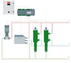
- Application example: Shows the EKE 80 connected to a PLC/AK-PC 782, ejectors, and valves.
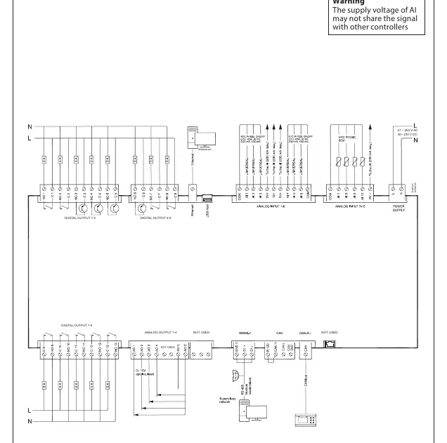
- Lower level connection: Details power supply, analog inputs, and communication ports.
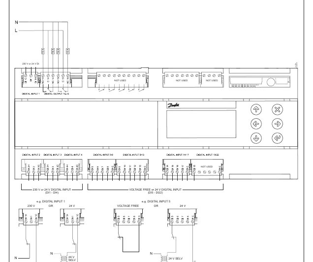
- Upper level connection: Details digital inputs (230 V or 24 V).
Model compatibility
- Compatible with Danfoss AK-PC 782A/AK-PC 782B or PLC.
- Ejectors 5 to 8 require an extension module.
- Not suitable for direct exposure to the Internet.

Manual page author
Michael Turner
Technical manual editor
Reviews PDF manuals for structure, safety notes, and practical product details so readers can find the right information quickly.