Home Appliances / Refrigerators
User Guide for Danfoss Ally 014G2479 Boiler Relay
Quick setup and installation guide for the Danfoss Ally Boiler Relay (014G2479). Includes wiring instructions, terminal definitions, and technical specifications.
Table of contents
Manual images
Jump to the sectionQuick guide from the manual
This document provides essential instructions for the professional installation and setup of the Danfoss Ally Boiler Relay. The device is designed for smart heating control and must be installed by trained professionals in accordance with local building regulations.
Installation
The installation process involves mounting the device and connecting it to the boiler and power supply:
- Remove the front cover of the relay.
- Mount the back plate directly to the wall or a wall box.
- Connect the N (Neutral) and L (Phase) terminals to the 230V mains power.
- Refer to your specific boiler's documentation to identify the correct terminals for connection.
Terminal Connections
The relay features specific terminals for wiring:
- N: Mains power 230VAC (neutral)
- L: Mains power 230VAC (phase)
- 1: No connection
- 2 (COM): Common of relay change-over switch
- 3 (ON): Connects to COM when heat is on (NO)
- 4 (OFF): Connects to COM when no heat is requested (NC)
- E: Extra terminal for fixing unused wires
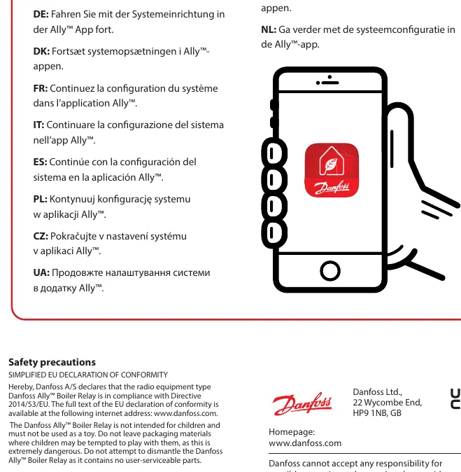
System Setup
After physical installation and wiring, complete the configuration using the Danfoss Ally App. Ensure you have followed the instructions provided with your gateway to download and set up the application.
Safety and Maintenance
The device is not a toy and must be kept away from children. Do not attempt to dismantle the unit, as it contains no user-serviceable parts. The device must be disposed of as electronic waste at the end of its service life.
Technical Specifications
- Power supply: 230V~ 50/60 Hz
- Output: Volt-free 3(1)A at 250V~
- Operating temperature: 0 °C to 40 °C
- Terminals: Max 2.5 mm² wires
- Transmission: 2.405 – 2.480 GHz, < 10 dBm
Manufacturer information
Danfoss A/S
Practical help
Common problems
Device not connecting to system
Ensure the gateway is set up correctly and follow the system configuration steps within the Ally App.
Unsure which boiler terminals to use
Consult the specific installation manual provided by your boiler manufacturer to identify the correct terminals.
Before use
- Ensure installation is performed by a trained professional.
- Verify compliance with local building regulations.
- Check that the power supply is 230V~ 50/60 Hz.
- Ensure wires do not exceed 2.5 mm².
- Download the Ally App via your gateway's instructions.
Specs in practice
- Volt-free output
- The relay provides a dry contact switch, meaning it does not supply voltage itself to the connected boiler circuit.
Images and diagrams
- The terminal table defines the function of each connection point (N, L, 1, 2, 3, 4, E).
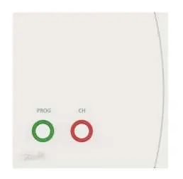
- The device front panel features two indicators: PROG (green) and CH (red).
Model compatibility
- Designed for use with 230V mains power.
- Not intended for use by children; do not use as a toy.
- Contains no user-serviceable parts.

Manual page author
Emily Carter
User documentation editor
Prepares concise manual descriptions and highlights the most useful setup, operation, and maintenance information for readers.