Home / Security
Installation Guide for Danfoss Aveo 015G4240 Tamperproof Thermostatic Sensor
A quick installation and configuration guide for the Danfoss Aveo Tamperproof thermostatic sensor. Learn how to mount the sensor, set temperature limits, and apply theft protection.
Table of contents
Manual images
Jump to the sectionQuick guide from the manual
This document provides essential installation and configuration steps for the Danfoss Aveo Tamperproof thermostatic sensor series. It covers physical mounting, setting maximum and minimum temperature limits to prevent unauthorized adjustments, and installing theft protection features.
Installation

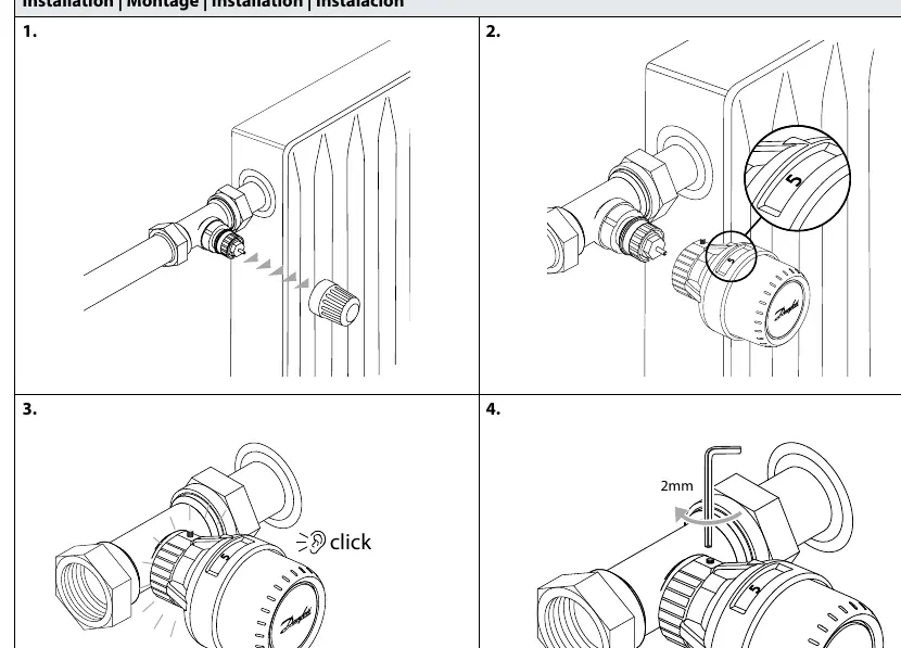
- Ensure the valve is fully open.
- Align the sensor with the valve body.
- Push the sensor firmly onto the valve until you hear a click.
- Secure the sensor using a 2mm Allen key to tighten the locking screw.
Temperature Limitation
The sensor allows for setting specific temperature ranges to restrict user control.
Maximum Temperature Limitation
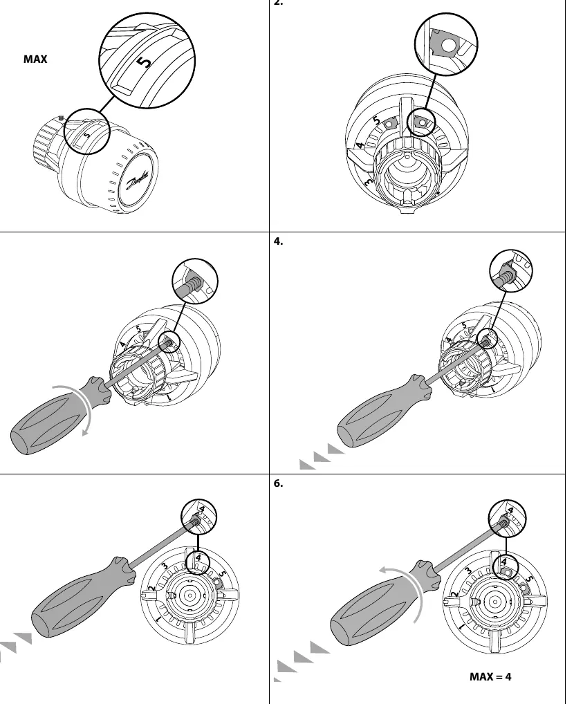
- Set the sensor to the desired maximum position.
- Locate the limitation pin inside the sensor housing.
- Use a screwdriver to adjust the pin position to the desired limit.
- Verify the setting; the sensor will now be restricted to the chosen maximum value.
Minimum Temperature Limitation
- Set the sensor to the desired minimum position.
- Access the internal limitation mechanism.
- Use a screwdriver to set the minimum limit pin.
- Confirm the setting to ensure the sensor cannot be turned below the selected minimum value.
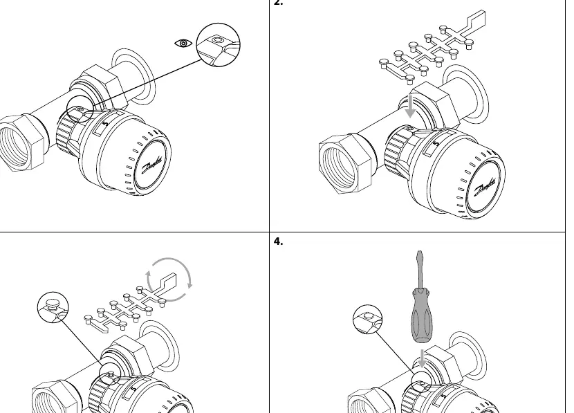
Theft protection
To prevent unauthorized removal of the sensor, use the dedicated theft protection kit (Code no. 013G1232). The process involves inserting the locking pins into the sensor housing and securing them to prevent the sensor from being unscrewed from the valve body.
Scale cover
A scale cover (Code no. 015G4952) can be applied to the sensor to hide the temperature markings, providing a cleaner look and further discouraging tampering.
Manufacturer information
Danfoss A/S
Practical help
Common problems
Sensor is loose or can be removed
Ensure the locking screw is tightened with a 2mm Allen key and consider installing the theft protection kit.
Temperature can be set too high or too low
Use the internal limitation pins to mechanically restrict the rotation range of the sensor head.
Before use
- Verify the valve is fully open before mounting.
- Ensure you have a 2mm Allen key for installation.
- Check if you need the theft protection kit (013G1232) for your installation environment.
- Decide if you need to set a maximum or minimum temperature limit.
Specs in practice
- 2mm Allen key
- Required tool for securing the sensor to the valve body.
Images and diagrams
- Page 1 shows the 4-step mounting process including the 'click' confirmation and 2mm screw tightening.
- Page 2 and 3 illustrate the step-by-step adjustment of internal pins for setting temperature limits.
- Page 4 details the insertion of theft protection pins.
- Page 5 shows the application of the scale cover.
Model compatibility
- Designed for Danfoss Aveo Tamperproof series.
- Compatible with standard Danfoss thermostatic valve bodies.

Manual page author
Emily Carter
User documentation editor
Prepares concise manual descriptions and highlights the most useful setup, operation, and maintenance information for readers.