Home / Security
Danfoss Gland Seal 013G0290 Replacement Guide
A quick guide for replacing the Danfoss Gland Seal 013G0290, including safety precautions, temperature requirements, and step-by-step removal and installation procedures for various sensor types.
Table of contents
Quick guide from the manual
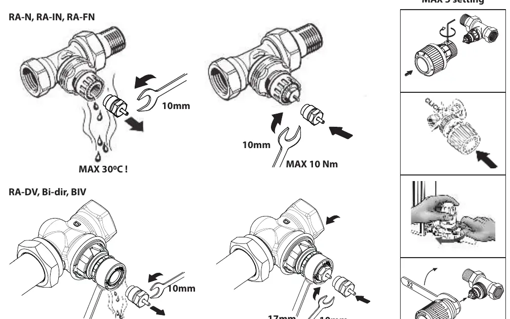
The Danfoss Gland Seal 013G0290 is designed to be replaced while the heating system is in operation, without the need to drain the water. Before starting, it is mandatory to reduce the flow temperature of the system to 30°C to prevent burns and ensure safety. Always perform a leak inspection after the new seal is installed.
Safety and Preparation
- Temperature limit: The system flow temperature must be reduced to 30°C before beginning the replacement.
- Leak check: Always verify the seal's integrity after installation.
- Operation: The seal can be replaced while the system is running.
Replacement Procedure
The process involves removing the existing sensor, replacing the gland seal, and remounting the sensor. Ensure you have the correct tools (10mm and 17mm wrenches).
Removing the Sensor
Depending on your sensor model (RA Allen, RA Click, RA Nut, or RTD), follow the specific removal method shown in the diagrams. For most models, ensure the sensor is set to the maximum setting (MAX 5) before removal.
Replacing the Gland Seal
- Use a 10mm wrench to unscrew the old gland seal.
- For RA-DV, Bi-dir, and BIV models, use a 17mm wrench to hold the fixed position while using the 10mm wrench to remove the seal.
- Insert the new gland seal.
- Tighten the new seal to a maximum torque of 10 Nm.
Mounting the Sensor
After the new seal is secured, reattach the sensor according to the specific mounting method for your model (e.g., clicking it back into place or tightening the nut). Ensure the sensor is properly seated.
Contact Information
Danfoss A/S, Heating Segment. Website: heating.danfoss.com. Phone: +45 7488 2222. Email: [email protected].
Official resources from the manual
Manufacturer information
Danfoss A/S
Practical help
Common problems
Water leakage after replacement
Ensure the gland seal is tightened to the correct torque (MAX 10 Nm) and verify the seal is seated correctly.
Risk of burns during replacement
Strictly follow the requirement to reduce the system flow temperature to 30°C before starting work.
Before use
- Reduce system flow temperature to 30°C.
- Identify your sensor type (RA Allen, RA Click, RA Nut, or RTD).
- Prepare a 10mm wrench.
- Prepare a 17mm wrench (required for RA-DV, Bi-dir, and BIV models).
- Ensure the sensor is set to the MAX 5 position before removal.
Images and diagrams
- The diagrams illustrate the specific removal and mounting steps for different sensor series (RA-N, RA-IN, RA-FN, RA-DV, Bi-dir, BIV, and RTD).
- The 10mm wrench is used for the gland seal itself.
- The 17mm wrench is used to hold the valve body in a fixed position for specific models.
Model compatibility
- Compatible with RA series (Allen, Click, Nut) and RTD sensors.
- Compatible with RA-DV, Bi-dir, and BIV valve bodies.

Manual page author
David Miller
Documentation analyst
Organizes user manual content into clear summaries, with attention to model details, product context, and everyday usability.