HVAC / Refrigeration Controllers
Installation Guide for Danfoss AK-CC55 Single Coil Case Controller
Quick installation and configuration guide for the Danfoss AK-CC55 Single Coil Case Controller. Includes wiring diagrams, parameter setup, and troubleshooting codes.
Table of contents
Manual images
Click an image to enlargeQuick guide from the manual
To start regulation quickly, follow these steps:
- Open parameter r12 and stop the regulation (set to 0).
- Select the application number based on the wiring diagrams (pages 2-4) and set it in parameter o61.
- Set the network address in o03.
- Select a set of presets from the Food type table using parameter r89.
- Set the desired cut-out temperature (r00), thermostat air temperature (r15), and alarm air temperature (A36).
- Select the refrigerant via parameter o30.
- Set the pressure transmitter range (o20, o21), defrost method (d01), interval (d03), and sensor (d10).
- Set the maximum defrost time (d04) and defrost stop temperature (d02).
- Open parameter r12 and start the regulation.
- Configure network settings (MODBUS scan or Lon RS485/Ethernet settings) if applicable.
Installation and Wiring
The controller is provided with factory labels for a generic application. Specific labels are provided for the selected application. Ensure that data communication cables are kept separate from high voltage cables, maintaining a distance of at least 10 cm. Use separate cable trays and avoid long cables at the low voltage DI input.
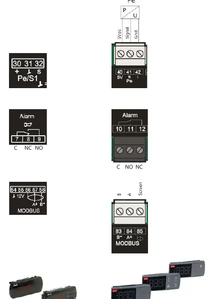
When replacing an AK-CC 550A with an AK-CC55, note that wiring principles have changed: pressure sensor connections, SPDT relay wiring (NO/NC switched), and Modbus connection schemes are different. Refer to the wiring diagrams on pages 2-4 for specific application connections.
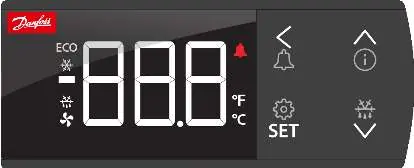
Operation with setting display
The AK-UI55 display shows values in three digits and allows temperature display in Celsius or Fahrenheit. The display features navigation arrows, an information button, and a SET button for configuration. A long press (3 seconds) on the SET button accesses the configuration menu. A long press on the arrow buttons can start a defrost or access the information menu.
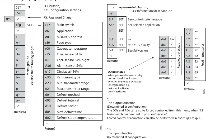
Parameters and Configuration
Parameters are grouped for easy access. The main switch (r12) controls regulation. Other key parameters include application selection (o61), refrigerant type (o30), and defrost settings (d01-d04). The controller supports forced control of outputs when the main switch is set to service mode.
Troubleshooting
In an error situation, the alarm LED on the front will be on and the alarm relay will be activated. Press the alarm button for 3 seconds to view the alarm report. Common messages include:
- Err: Sensor error.
- Err1: Display cannot load data from the controller.
- Err2: Lost display communication.
- ALA: Alarm button activated.
- Loc: Configuration is locked (unlock by pressing up and down arrows simultaneously for 3 seconds).
- PS: Password required for access.
Technical Data
The controller operates on 115 V / 230 V, 50/60 Hz with a power consumption of 5 VA. It is designed for DIN rail mounting and has an IP20 enclosure rating. The clock battery backup provides 4 days of power reserve. Digital inputs require gold-plated contacts and a maximum cable length of 15 m.
Manufacturer information
Danfoss A/S
Practical help
Common problems
Err
Sensor error; check the sensor for correct operation.
Err1
Display cannot load data; disconnect and then reconnect the display.
Err2
Lost display communication.
Loc
Configuration is locked; unlock by pressing the 'up arrow' and 'down arrow' simultaneously for 3 seconds.
A45
Main switch set to OFF; check if the controller is set to Stop/Manual or if a digital input has stopped control.
Before use
- Ensure data communication cables are kept separate from high voltage cables (min 10cm distance).
- Verify supply voltage (115V / 230V, 50/60 Hz).
- Check that all sensors (S2-S6) are of the same type.
- Ensure the controller is mounted on a DIN rail.
- Select the correct application number based on the wiring diagrams.
Specs in practice
- Supply voltage
- 115 V / 230 V, 50/60 Hz
- Power consumption
- 5 VA
- Enclosure rating
- IP20
- Clock battery backup
- 4 days
Images and diagrams
- Wiring diagrams (pages 2-4) show connections for various applications (1-9).
- The display interface (page 8) allows navigation, setting changes, and alarm resets.
- Parameter grouping (page 9) outlines the menu structure for configuration.
Model compatibility
- Not compatible with two EC coils on one AKV output.
- Pressure transmitter can be shared between AK-CC 550 and AK-CC55.
- DI2 defrost coordination can be wired between AK-CC 550 and AK-CC55.

Manual page author
Michael Turner
Technical manual editor
Reviews PDF manuals for structure, safety notes, and practical product details so readers can find the right information quickly.