HVAC / Refrigeration Components
Installation Guide for Danfoss COM 10C and 20C Oil Level Regulator
Comprehensive installation and wiring guide for the Danfoss COM 10C and 20C oil level regulators. Includes technical specifications, mounting procedures, electrical connection diagrams, and essential safety instructions for refrigeration...
Table of contents
Manual images
Click an image to enlargeQuick guide from the manual
The Danfoss COM 10C and 20C are oil level regulators designed for refrigeration systems and heat pumps. Before installation, ensure the refrigerant circuit area is fully depressurized. The device must be installed horizontally with a tolerance of +/- 1 degree. Always remove the transport lock before installation and ensure all sealing surfaces are clean. The device is maintenance-free under normal conditions, but the filter in the oil connection may require cleaning or replacement.
Technical Specifications
The following specifications apply to the COM 10C and 20C models:
- Compatible Refrigerants: HFC, CO2, HC
- Compatible Oils: Mineral, Synthetic, Ester oils
- Max Operating Pressure: 60 bar (COM 10C) / 130 bar (COM 20C)
- Supply Voltage: 24V AC or 230V AC (50Hz)
- Protection Class: IP65
- Filter: 100 micron mesh 80
- Vibration Resistance: Max 4g, 10-250Hz
Installation
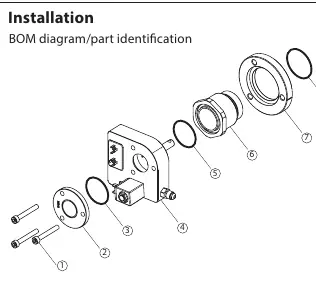
The installation process involves assembling the regulator onto the compressor. Ensure you have all parts listed in the BOM diagram: screws, sight glass, O-rings, adapter, and flange ring. Follow these steps:
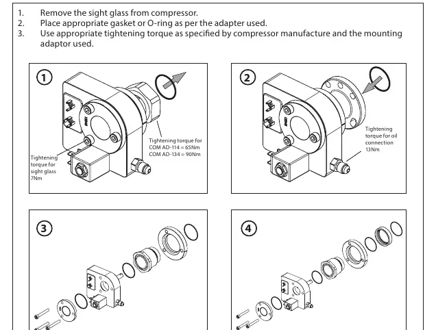
- Remove the sight glass from the compressor.
- Place the appropriate gasket or O-ring as per the adapter used.
- Use the appropriate tightening torque as specified by the compressor manufacturer and the mounting adapter used.
Electrical Connection
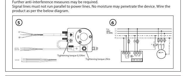
Ensure compliance with country-specific regulations. The operating voltage range must not be exceeded. If the line length exceeds 6 meters, the signal must be evaluated for interference and EMC. Signal lines must not run parallel to power lines. Ensure no moisture penetrates the device. Refer to the wiring diagrams provided in the manual for specific connections for 24V AC and 230V AC systems.
Service and Maintenance
The devices are maintenance-free when used under the conditions mentioned in this manual. In case of a defect, replace the device. To clean the filter in the oil connection or replace the oil connection, the refrigerant circuit area must be depressurized. Switch off system power and remove the product in reverse order of installation.
Safety and Operational Instructions
Installation must be carried out by educated and trained professional experts. The product must be gas-proof before operation. Ensure the test pressure is not exceeded. The coil becomes hot during operation; do not remove the plug from the coil when the device is powered on. For CO2 refrigeration systems, specific skills and training are required due to high-pressure levels and the risk of bursting at standstill.
Manufacturer information
Danfoss A/S
Practical help
Common problems
Device not functioning or defective
Check if permissible operating temperatures are exceeded. If the device is defective, it must be replaced.
Oil level issues
Ensure oil is always upstream of the regulator (no discharge gas). Check the oil level on the sight glass after long periods of standstill.
Signal interference
If line length is greater than 6m, evaluate for interference and EMC. Ensure signal lines do not run parallel to power lines.
Before use
- Depressurize the refrigerant circuit area.
- Check parts for completeness against the BOM diagram.
- Ensure sealing surfaces are clean.
- Align the product horizontally (tolerance +/- 1 degree).
- Remove transport lock before installation.
- Verify that the test pressure will not be exceeded.
Specs in practice
- Max Operating Pressure
- 60 bar for COM 10C; 130 bar for COM 20C.
- Protection Class IP65
- The device is dust-tight and protected against water jets.
- Alarm contact
- Max 3A, 230V AC dry contact.
Images and diagrams
- BOM diagram identifies the assembly sequence of screws, sight glass, O-rings, adapter, and flange ring.
- Wiring diagram 5 illustrates connections for 24V AC and 230V AC power supplies.
- Wiring diagram 6 illustrates connection to a 3-phase 400V system.
Model compatibility
- Compatible with HFC, CO2, and HC refrigerants.
- Compatible with Mineral, Synthetic, and Ester oils.
- Intended for refrigeration systems and heat pumps according to EN 378.

Manual page author
Emily Carter
User documentation editor
Prepares concise manual descriptions and highlights the most useful setup, operation, and maintenance information for readers.