HVAC / Refrigeration Controllers
Danfoss RT 112W Pressure Switch
Installation and setup guide for the Danfoss RT 112W pressure switch. Includes wiring diagrams, mounting instructions, technical specifications, and configuration details for industrial pressure monitoring.
Table of contents
Manual images
Click an image to enlargeQuick Installation Guide
The Danfoss RT 112W is an industrial pressure switch designed for pressure monitoring with automatic reset. For proper operation, ensure the unit is mounted in an upright position. If the pressure connection is exposed to high temperatures (above 100°C), use a damping loop (e.g., 10mm Cu tube) to protect the control. To maintain the IP65 enclosure rating, the plug must be correctly assembled as shown in the installation diagrams.
Installation Requirements
Proper installation is critical for the longevity and accuracy of the pressure switch:
- Orientation: Always mount the unit in an upright position with the connector facing upwards.
- Pressure Connection: Ensure the connection is made so that impurities in the line do not block the pressure inlet.
- Temperature Protection: If the medium temperature exceeds 100°C, install a damping loop or a water-filled pipe loop to act as a temperature barrier.
- Frost Protection: In water plants, position the control to avoid exposure to frost. Using an air cushion is recommended.
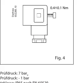
- IP65 Rating: To ensure the IP65 enclosure grade, the plug must be assembled according to the provided instructions.
Wiring and Connections
The pressure switch features specific terminals for electrical connection:
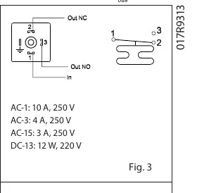
- 1: Input
- 2: Normally Closed (NC)
- 3: Normally Open (NO)
- Ground: Connected to the chassis of the pressure switch
Settings and Adjustment
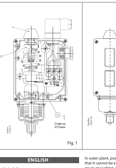
The pressure switch is configured to provide a make or break function on rising pressure. Adjustments are made using the setting knob (1) while simultaneously reading the value on the main scale (2).
Technical Specifications
- Ambient Temperature: -40°C to 70°C
- Medium Temperature: Max 150°C
- Max Test Pressure: 7 bar
- Min Test Pressure: -1 bar
- Enclosure Rating: IP65 (acc. to EN 60529)
- Contact Load: Refer to the wiring diagram (Fig 3) for AC/DC ratings.
Manufacturer information
Danfoss A/S
Practical help
Common problems
Pressure inlet blockage
Ensure the pressure connection is made so that impurities in the line do not block the inlet.
Overheating of the pressure connection
If the connection point exceeds 100°C, install a damping loop or a water-filled pipe loop (e.g., 10mm Cu tube) as a temperature barrier.
Frost damage in water plants
Position the pressure control to avoid frost exposure, for example, by letting it operate on an air cushion.
Before use
- Verify the unit is mounted in an upright position.
- Ensure the pressure connection is free of impurities.
- Install the plug correctly to maintain IP65 protection.
- Check that the medium temperature does not exceed 150°C.
- Confirm the ambient temperature is within the -40°C to 70°C range.
Specs in practice
- Max. test pressure 7 bar
- The maximum pressure the device can withstand during testing without damage.
- W designation
- Indicates pressure monitoring with automatic reset.
Images and diagrams
- Fig 1: Overview of the pressure switch assembly and connection points.
- Fig 3: Wiring diagram detailing Input, NC, and NO terminals.
- Fig 4: Assembly instructions for the plug to ensure IP65 rating.
Model compatibility
- Designed for industrial pressure monitoring.
- Requires specific damping measures for high-temperature applications (>100°C).

Manual page author
Emily Carter
User documentation editor
Prepares concise manual descriptions and highlights the most useful setup, operation, and maintenance information for readers.