HVAC / Refrigeration Controllers
User Manual for Danfoss ERC 111A Refrigeration Controller
Comprehensive user manual for the Danfoss ERC 111A refrigeration controller. Includes installation, wiring, programming, parameter settings, and troubleshooting guide for technicians and OEMs.
Table of contents
Manual images
Click an image to enlargeQuick Guide from the Manual
The Danfoss ERC 111A is an electronic refrigeration controller designed for commercial fridges, freezers, and bottle coolers. This manual is intended for OEMs and technicians. Key operations include configuring parameters via the front panel buttons or using the KoolProg software with a KoolKey. The device supports three password-protected access levels: shop, technician, and OEM.
Product Overview
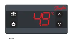
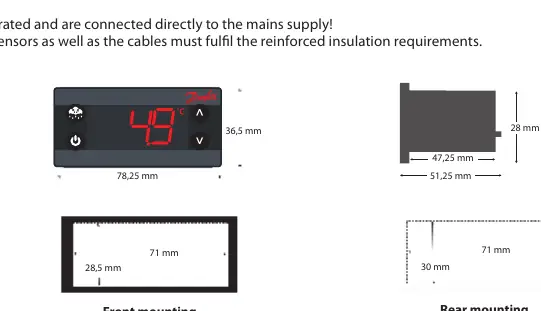
The controller features an LED display, four programmable buttons, and modular connectors. It can be mounted via front panel mounting (using a frame) or rear mounting (using clips). The device supports two temperature sensors: S1 (cabinet temperature) and S2 (defrost/evaporator temperature).
Installation and Connections
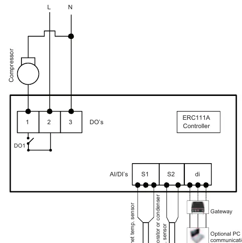
Wiring: The controller operates on 100-240 V AC. The wiring diagram includes connections for the compressor relay (DO1), cabinet temperature sensor (S1), evaporator/condenser sensor (S2), and digital input (di). Inputs are not galvanically separated; ensure cables meet reinforced insulation requirements.
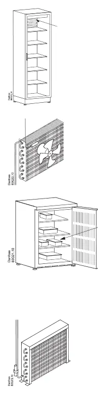
Sensor Placement:
- Control Sensor: For coolers with fans, place in the return air to the evaporator. For coolers without fans, place on the side-wall, 10 cm from the back and 1/3 from the bottom.
- Condenser Sensor: Place at the liquid side of the condenser using a metal bracket or tape to ensure thermal conductivity.
Programming and Operation
Programming Tools: Configuration can be performed via the front panel buttons, KoolProg software (using KoolKey as a gateway), KoolKey as a copy key, or a Mass Programming Key (EKA 201).
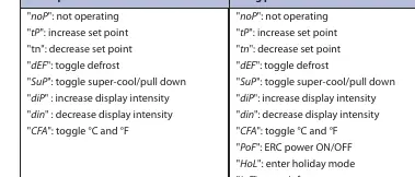
Manual Operation: Use the front panel buttons to adjust set points, acknowledge alarms, or enter the menu. Accessing the menu requires holding the up/down buttons for 5 seconds and entering a password.
Info Menu: Provides access to critical data points, including highest, lowest, and average cabinet air temperatures since the last power-on, and active alarms.
Menu and Parameter Settings
The controller offers extensive parameter settings categorized by function:
- Thermostat (tHE): Set point, differential, and temperature limits.
- Pull Down (Pud): Settings for rapid cooling performance.
- Defrost (dEF): Type, intervals, duration, and termination temperature.
- Compressor (CoP): Voltage protection, error handling, and timing delays.
- Condenser (Con): Protection settings (requires condenser sensor).
- Display (diS): Intensity, units, resolution, and offsets.
- Alarm (ALA): High/low temperature alarms, delays, and buzzer duration.
- Assignments (ASi): Configuration of inputs and outputs.
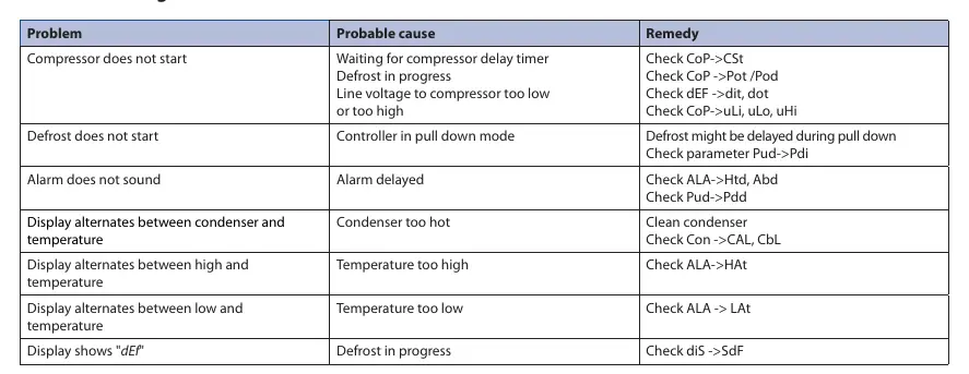
Troubleshooting
If the compressor does not start, check the delay timer, line voltage, or if a defrost cycle is in progress. If the display alternates between condenser and temperature, the condenser may be too hot; clean the condenser. Error codes E01 and E02 indicate sensor failures for S1 and S2, respectively.
Technical Specifications
- Power Supply: 100-240 V AC, average 0.7 W.
- Inputs: 2 analogue (digital), user-specific assignment.
- Outputs: Compressor relay (16A resistive at 120V AC, 10A at 240V AC).
- Ingress Protection: Front IP65, Rear IP00/IP31.
- Operating Conditions: 0 to 55 °C, 93% RH non-condensing.
Manufacturer information
Danfoss A/S
Practical help
Common problems
Compressor does not start
Check for compressor delay timer, active defrost, or line voltage issues (too low/high).
Defrost does not start
Check if the controller is in pull-down mode or verify parameter settings (Pud->Pdi).
Alarm does not sound
Check alarm delay settings (ALA->Htd, Abd) or pull-down delay (Pud->Pdd).
Display alternates between condenser and temperature
Condenser is too hot. Clean the condenser and check Con->CAL, CbL settings.
Before use
- Verify power supply is 100-240 V AC.
- Ensure correct sensor placement (Control sensor in return air, Condenser sensor at liquid side).
- Confirm access level (Shop, Technician, OEM) required for configuration.
- Check if KoolProg software is needed for advanced parameter setup.
- Ensure all sensors and cables meet reinforced insulation requirements.
Images and diagrams
- Wiring diagram illustrates connections for compressor relay (DO1), sensors (S1, S2), and digital input (di).
- Dimensions diagrams provide cut-out and mounting requirements for front and rear installation.
Model compatibility
- Requires Danfoss NTC sensors.
- Compatible with KoolKey (EKA 200) and Mass Programming Key (EKA 201).
- Condenser sensor is optional.

Manual page author
Michael Turner
Technical manual editor
Reviews PDF manuals for structure, safety notes, and practical product details so readers can find the right information quickly.