HVAC / Refrigeration Controllers
User Manual for Danfoss ERC 112D VSC Refrigeration Controller
Comprehensive user guide for the Danfoss ERC 112D VSC electronic refrigeration controller. Includes installation, wiring, parameter configuration, troubleshooting, and sensor placement instructions for OEMs and technicians.
Table of contents
Manual images
Click an image to enlargeQuick Guide
The Danfoss ERC 112D VSC is an electronic refrigeration controller designed for commercial fridges and freezers equipped with variable speed compressors. This guide is intended for OEMs and technicians for programming and installation purposes. It is not intended for end-users.
Product Overview
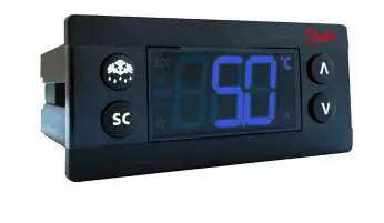
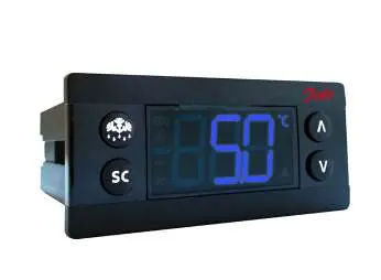
The controller features an LED display and four buttons for operation. The upper left button is Defrost, and the lower left button is Super chill. The unit uses two identical clips for rear mounting or a front frame for front mounting.
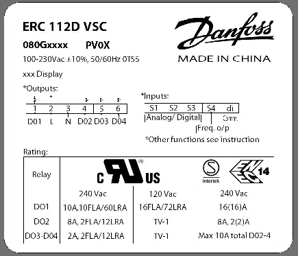
Inputs and Outputs
- S1: Cabinet temperature sensor.
- S2: Defrost temperature sensor (mount on evaporator).
- S3: Condenser temperature sensor, light sensor, or motion sensor.
- S4: Frequency signal for variable speed compressor (5 V, 0-200 Hz).
- di: Door signal or motion sensor.
Installation and Connections
Inputs and outputs are configurable. The controller supports various applications, including light/motion/door control and condenser/door/motion control. Ensure sensors are placed correctly: control sensors in return air, evaporator sensors where ice melts last, and condenser sensors on the liquid side of the condenser.
Programming
The controller can be programmed in three ways:
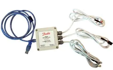
- KoolProg Software: PC-based software for parameter setting via a USB gateway.
- USB Programming Key: Used for reading/writing parameters in a laboratory setting.
- Docking Station: Used for mass programming on an assembly line.
Operation and Parameters
Access to parameters is password-protected with three levels: Level 1 (Shop), Level 2 (Technicians), and Level 3 (OEMs). To access the menu, press the up and down arrows together for 5 seconds.
Parameter Groups
- Thermostat (tHE): Set point, differential, and limits.
- Fan (FAn): Control methods, delays, and cycles.
- Light (Lig): Cabinet light control and delays.
- Pull Down (Pud): Settings for rapid cooling.
- Defrost (dEF): Types, intervals, and durations.
- Compressor (CoP): Speed settings and frequency.
- Condenser (Con): Protection settings and alarms.
- Display (diS): Intensity, units, and resolution.
- Alarm (ALA): High/low temperature alarms and delays.
- ECO (ECS/ECA): Energy-saving strategies.
Troubleshooting
If the compressor does not start, check the frequency cable continuity and connections. If the fan does not start, verify the door contact status. If the display brightness is weak, the ambient light sensor may need replacement. Refer to the alarm codes (e.g., Hi, Lo, Con, E01) on the display to identify specific faults.
Technical Specifications
The controller operates on a 100-240 V AC switch-mode power supply. It features an IP65 front protection rating. Inputs are not galvanically isolated and connect directly to the mains supply; ensure all sensors and cables meet reinforced insulation requirements.

Manufacturer information
Danfoss A/S
Practical help
Common problems
Compressor does not start
Check frequency cable continuity and connections at the controller and drive side.
Fan does not start
Check if the door is open or if the door contact is defective.
Defrost does not start
Check if the controller is in pull-down mode; defrost may be delayed.
Display brightness is weak
The ambient light sensor may be broken; replace the sensor.
Before use
- Verify power supply is 100-240 V AC.
- Ensure correct sensor placement (Control, Evaporator, Condenser).
- Check wiring against the specific application diagram.
- Configure inputs/outputs via KoolProg or buttons.
- Set access level passwords.
Images and diagrams
- Wiring diagrams illustrate connections for Light/Motion/Door and Condenser/Door/Motion configurations.
- Dimensions diagrams provide measurements for front and rear mounting.
Model compatibility
- Requires Danfoss NTC sensors.
- Inputs and outputs are configurable.
- Not intended for end-users; for OEM/technician use only.

Manual page author
David Miller
Documentation analyst
Organizes user manual content into clear summaries, with attention to model details, product context, and everyday usability.