Industrial / Valves
Installation Guide for Danfoss DSV 1 & DSV 2 Double Stop Valve
A comprehensive installation and maintenance guide for the Danfoss DSV 1 and DSV 2 double stop valves. Includes detailed procedures for mounting, welding, operating, and performing maintenance such as packing gland replacement and pressure...
Table of contents
Manual images
Click an image to enlargeQuick guide from the manual
The Danfoss DSV 1 and DSV 2 are double stop valves designed for use in closed refrigeration circuits. This guide covers the essential installation, operation, and maintenance procedures required for safe and efficient use. Always ensure the valve is protected from pressure transients like liquid hammer and that the piping system is designed to avoid liquid traps.
Installation
Refrigerants: Suitable for HCFC, HFC, R717 (Ammonia), and R744 (CO2). Flammable hydrocarbons are not recommended.
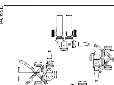
Mounting: The valve must be installed with the spindle in a horizontal position. Ensure the valve housing is free from external stresses after installation. Double stop valves must not be mounted in systems where the outlet side is open to the atmosphere; the outlet must always be connected to safety valves, the system, or properly capped off.
Welding: If using welding fittings, dismount them during the welding process. If welding directly on the valve housing, remove the bonnet to prevent damage to O-rings and the Teflon gasket. Ensure the temperature between the valve body and bonnet does not exceed +50°C (+302°F) during welding. Clean the valve internally to remove welding debris before reassembly.
Operating instructions
Valves should be opened by hand without the use of tools. The flow direction should ideally follow the arrow on the valve body for optimum conditions, though reverse flow is acceptable with a slight reduction in Kv/Cv values.
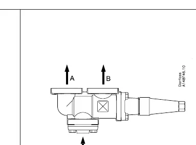
- Clockwise rotation: Connects inlet socket C to outlet B.
- Anticlockwise rotation: Connects inlet socket C to outlet A.
Maintenance
Packing gland replacement: As a general rule, do not remove the packing gland if there is internal pressure. If necessary, it can be removed under pressure by following these steps:
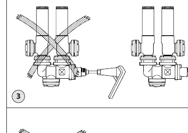
- Backseating: Turn the spindle counter-clockwise until it stops to activate the backseating function.
- Pressure equalization: Fasten a hand wheel to the top of the spindle. Slowly unscrew the packing gland to equalize pressure.
- Removal: Once pressure is equalized, the packing gland can be removed. Check the spindle for scratches or impact marks. If the Teflon cone rings are damaged, replace the entire cone assembly.
Always use original Danfoss parts for replacements, including packing glands, O-rings, and gaskets.
Technical specifications
Temperature range: -50/+100°C (-58/+212°F).
Max working pressure: 40 bar g (580 psi g).
Tightening: Always use a torque wrench to tighten the bonnet and packing gland to the values specified in the product tables.
Manufacturer information
Danfoss A/S
Practical help
Common problems
Welding debris inside the valve
Clean the valve internally to remove all welding debris and dirt before reassembly.
Pressure behind the packing gland during service
Perform backseating by turning the spindle counter-clockwise until it stops, then use a hand wheel to slowly equalize pressure while unscrewing the gland.
Damaged Teflon cone rings
If the Teflon cone rings are damaged, the entire cone assembly must be replaced.
Before use
- Verify refrigerant compatibility (HCFC, HFC, R717, R744).
- Ensure the valve is installed in a closed circuit.
- Check that the spindle is in a horizontal position.
- Remove all welding debris from pipes and valve body.
- Ensure the cone is screwed back towards the bonnet before installation.
- Check that O-rings are free of scratches or impact marks.
Specs in practice
- Temperature range
- -50/+100°C (-58/+212°F)
- Max working pressure
- 40 bar g (580 psi g)
Images and diagrams
- Fig 1: Correct horizontal installation position.
- Fig 2: Recommended flow direction.
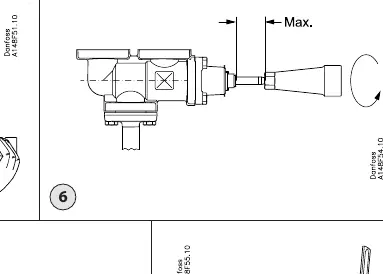
- Fig 6: Backseating procedure to seal the valve.
- Fig 7: Pressure equalization procedure.
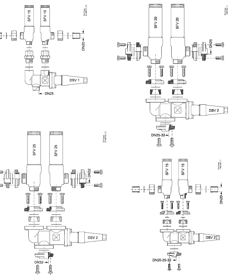
- Fig 10: Mounting configuration with safety valves (SFV).
Model compatibility
- Not suitable for flammable hydrocarbons.
- Only for use in closed circuits.
- Outlet side must not be open to the atmosphere.

Manual page author
David Miller
Documentation analyst
Organizes user manual content into clear summaries, with attention to model details, product context, and everyday usability.