Industrial / Valves
Danfoss 027R9528 High Pressure Float Valve Instructions
Quick guide for the Danfoss 027R9528 High Pressure Float Valve. Includes installation steps, welding procedures, maintenance, and technical specifications.
Table of contents
Manual images
Click an image to enlargeQuick guide from the manual
The Danfoss High Pressure Float Valve (HFI) is designed for use in closed refrigeration circuits. It is compatible with common non-flammable refrigerants, including R717. The valve is designed to withstand high internal pressure and must be protected from pressure transients like liquid hammer. Key operational requirements include maintaining a horizontal mounting position with the outlet connection facing vertically downwards and ensuring the valve housing is free from external stresses after installation.
Installation
Before installation, ensure the piping system is designed to avoid liquid traps and hydraulic pressure caused by thermal expansion. The flow direction must follow the arrows indicated on the valve.
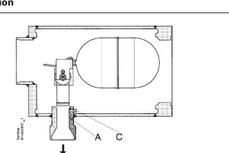
- Welding: Remove the float assembly before welding. Dismount the end cover, remove transport packing, unscrew the screw (pos. C), and lift out the float assembly. Weld the outlet connection (pos. A) into the plant. Clean the interior of the valve to remove welding debris before reassembly.
- Mounting: Mount the valve horizontally with the outlet connection (pos. A) pointing vertically downwards.
Assembly
Ensure all welding debris and dirt are removed from pipes and the valve body before assembly.
- Replace the float assembly in the outlet branch.
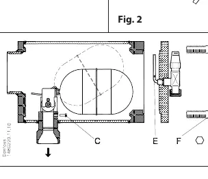
- Tighten the screw (pos. C). Ensure the float assembly is fully seated in the outlet connection and the float ball is positioned in the middle of the housing for unrestricted movement.
- Remount the end cover with the purge valve and pipe.
- Ensure the ventilating pipe (pos. E) is placed vertically upwards.
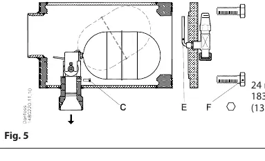
- Use a torque wrench to tighten the screws (pos. F) to 183 Nm (135 lb-feet).
Maintenance
Regular maintenance is required to ensure proper operation.
- Purging: Incondensable gases may accumulate in the upper part of the valve. Purge these gases using the purge valve (pos. G).
- Replacing Float Assembly: Before opening the valve, the system must be evacuated and pressure equalized to atmospheric pressure using the purge valve (pos. G). Remove the end cover, unscrew the float assembly (pos. C), and lift it out. Install the new assembly, tighten the screw, and remount the end cover. Ensure the purge valve is closed before pressurizing the system.
Technical Specifications
- Temperature Range: -50 to +150°C (-58 to +302°F).
- Max Working Pressure: 25 bar g (363 psi g).
- Tightening Torque: 183 Nm (135 lb-feet).
- Refrigerant Compatibility: Standard design for R717 (density 500-700 kg/m3).
Manufacturer information
Danfoss A/S
Practical help
Common problems
Incondensable gases accumulating in the valve
Purge the gases using the purge valve (pos. G).
Heavy demand at low temperature
Check the velocity in the outlet branch; if necessary, increase the diameter of the pipe welded to the outlet branch.
Float assembly restricted
Ensure the float assembly is positioned in the middle of the housing so it can move without restriction.
Before use
- Verify refrigerant compatibility (standard design is for R717).
- Ensure the system is evacuated and pressure is equalized before opening the valve.
- Check that the purge valve is closed before pressurizing the system.
- Ensure the ventilating pipe (pos. E) is placed vertically upwards.
- Verify that the valve housing is free from external stresses after installation.
Specs in practice
- Temperature range
- -50/+150°C (-58/+302°F)
- Max working pressure
- 25 bar g (363 psi g)
- Tightening torque
- 183 Nm (135 lb-feet) for screws (pos. F)
Images and diagrams
- Fig 1: Installation orientation with outlet connection A.
- Fig 3: Assembly showing screw C and ventilating pipe E.
- Fig 4: Purge valve G location for maintenance.
- Fig 5: Maintenance steps for replacing the float assembly.
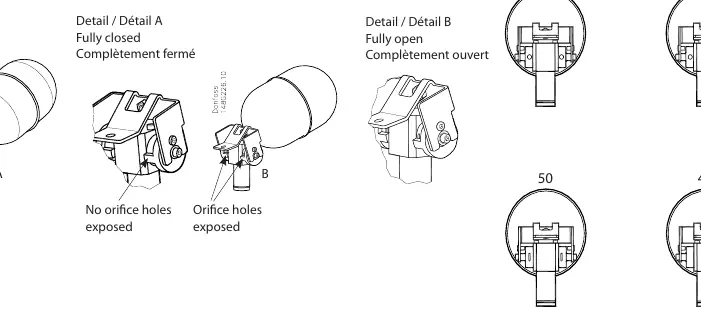
- Fig 6: Detail of float positions (fully closed vs fully open).
Model compatibility
- Designed for R717 (density 500-700 kg/m3).
- Not recommended for flammable hydrocarbons.
- Only for use in closed circuits.

Manual page author
Emily Carter
User documentation editor
Prepares concise manual descriptions and highlights the most useful setup, operation, and maintenance information for readers.