Industrial / Gas Detection
Installation Guide for Danfoss 148R9637 Gas Detection Controller
Quick installation and configuration guide for the Danfoss 148R9637 gas detection controller. Includes wiring diagrams, system capacity limits, and operational mode explanations.
Table of contents
Manual images
Click an image to enlargeQuick guide from the manual
This document provides installation and configuration guidelines for the Danfoss 148R9637 gas detection controller unit and its expansion modules. It is intended for professional installation in residential, commercial, and industrial areas. Note that this device must not be used in potentially explosive atmospheres.
System overview and capacity
The controller unit acts as a warning and control hub for toxic and combustible gases. Key system capacities include:
- Expansion modules: Up to 7 modules per controller.
- Sensors: Up to 96 digital sensors via field bus and up to 32 analog inputs (4-20 mA).
- Total capacity: Maximum of 128 sensors per controller, regardless of the number of expansion modules.
Wiring and installation
Proper wiring is critical for system stability. Adhere to the following requirements:
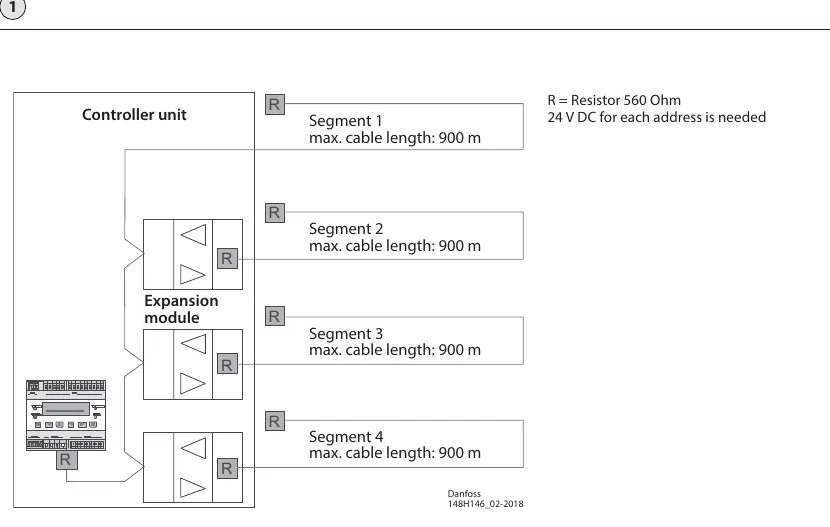
- Cable length: Maximum cable length is 900 meters per segment.
- Termination: A 560 Ohm resistor is required for each address.
- Power: The system operates on 24 V DC.
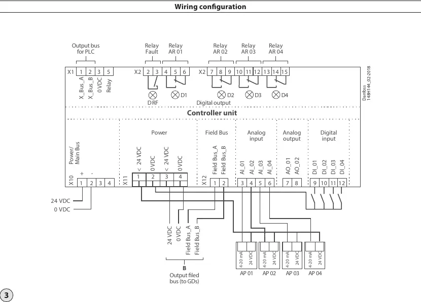
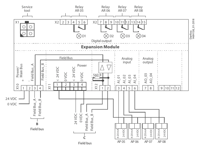
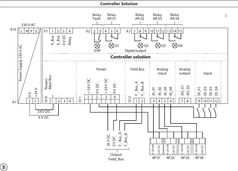
- Connections: Wiring configurations are provided for the controller unit, expansion modules, and field bus connections. Ensure all connections match the provided wiring diagrams for relays, inputs, and outputs.
Operational modes
The controller operates in several modes to ensure safety and monitoring:
- Normal Mode: Continuous polling of active sensors with scrolling display.
- Alarm Mode: Activated when gas concentration exceeds thresholds. Alarm relays are triggered, and LEDs flash.
- Fault Mode: Triggered by communication errors, out-of-range analog signals, or internal function errors. Requires manual acknowledgment after the cause is removed.
- Restart Mode (Warm-up): A running-in period for sensors to stabilize. No alarms are active during this time.
- Service Mode: Used for commissioning, calibration, and repair. Alarms for affected devices are held, but new alarms are suppressed.
UPS functionality
The controller supports an optional UPS (Controller solution uptime) accessory. The system monitors supply voltage and automatically switches to battery power during a failure. The battery is charged when main power is available and protected against deep discharge. No specific parameter settings are required for this functionality.
Manufacturer information
Danfoss A/S
Practical help
Common problems
Pseudo alarm during start-up
Sensors require a running-in period. Ensure the correct power-on time is configured in the controller to prevent unwanted alarms during this phase.
Fault relay activated
Check for incorrect communication, analog signals outside the 3.0-21.2 mA range, or internal function errors. Acknowledge the error manually in the 'Error Status' menu after resolving the cause.
Before use
- Verify that the total number of sensors does not exceed 128.
- Ensure cable length per segment is within the 900m limit.
- Confirm 560 Ohm resistors are installed as required for the field bus.
- Check that the 24 V DC power supply is stable.
- Ensure the environment is not potentially explosive.
Specs in practice
- Max cable length
- 900 meters per segment for field bus communication.
Images and diagrams
- Wiring diagrams detail connections for power, field bus, analog inputs/outputs, and relays.
- The UPS diagram illustrates the battery backup connection for continuous operation.
Model compatibility
- Compatible with up to 7 expansion modules per controller.
- Not suitable for use in potentially explosive atmospheres.

Manual page author
David Miller
Documentation analyst
Organizes user manual content into clear summaries, with attention to model details, product context, and everyday usability.