General / Other Manuals
Solenoid Coil Type BI Installation Guide
Installation and safety guide for Danfoss Type BI solenoid coils. Includes wiring, earthing, valve compatibility, and technical specifications for explosive atmosphere applications.
Table of contents
Manual images
Jump to the sectionQuick guide from the manual
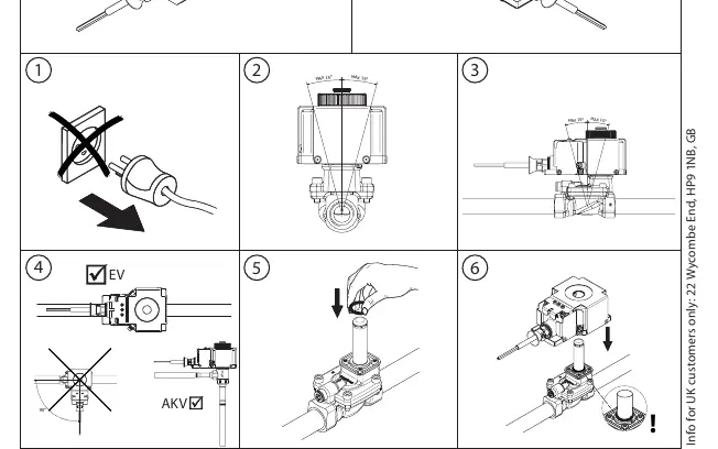
This document provides installation and safety instructions for the Danfoss Type BI solenoid coil. The coil is designed for use in potentially explosive atmospheres. Key requirements include ensuring the coil is protected against impact, maintaining correct orientation during installation, and strictly following the earthing procedures. The device is not field-repairable; if it fails, it must be replaced.
Safety instructions
Installation, start-up, and operation must be performed only by suitably qualified personnel in compliance with national safety regulations and explosion-proof standards (Ex mb IIC T4 Gb). Specific safety conditions include:
- Protect the coil against impact during use.
- Protect the coil against direct sunlight and other ultraviolet sources.
- Disconnect power before dismounting the coil.
- Ensure the cable is not handled or flexed if the ambient temperature is below 0 °C.
- The permitted process medium temperature range is -40 °C to +90 °C.
Installation and mounting
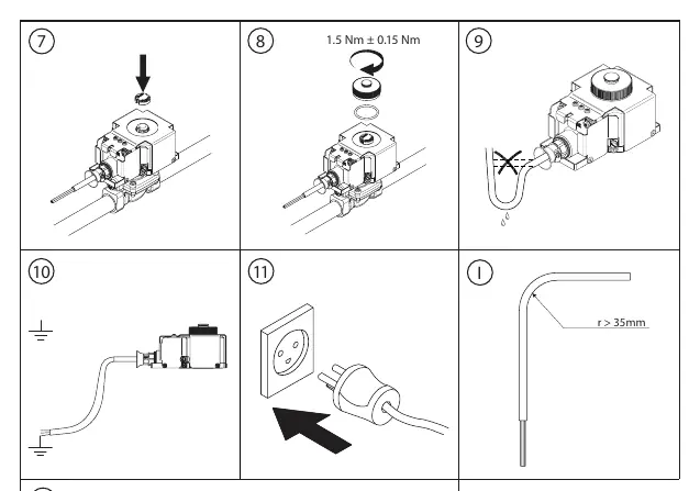
The coil must be installed in the specific orientation shown in the manual (refer to the installation diagrams). Ensure the cable is used only for fixed installation with a minimum bending diameter of 35 mm. The cable jacket is made of PVC and is rated for temperatures between -40 °C and 90 °C.
Earthing and wiring
The product is provided with both a yellow/green PE conductor and an external earth terminal. These must not be used simultaneously.
- If the external earth connection is used, the PE conductor must be cut off, isolated, and not connected.
- If the PE conductor is used, the external earth terminal must be left without any connection.
- For the external earth terminal, the earth core must be at least 4 mm².
- The screw for the external PE must be mounted with a torque of 1.5 Nm ± 0.2.
- External earth conductors must be physically secured close to the coil connection to prevent loosening or twisting.
Compatibility
The coil is compatible with specific valve combinations. It can be installed with valves in group A, group B, or valves compatible with both. Examples of compatible valves include EVR, EV220B, EV250B, EV222B, EV224B, EVRA, and EVRS(T) series. Always verify the specific valve model against the compatibility list provided in the manual.
Technical specifications
- Ambient temperature: -40 °C to +40 °C
- Media temperature: -40 °C to +90 °C
- Humidity: 0 - 97%
- Protection degree: IP67
- Voltage tolerance: +6 / -10%
- Connection: 3-Wire cable 3 x 0.75mm²
- Weight: 1.0 kg
- Mode of operation: Type 1 action (EN60730-1)
Manufacturer information
Danfoss A/S
Practical help
Common problems
Coil failure
The coil is a non-detachable, non-repairable unit. If it fails, it must be replaced with a new coil.
Incorrect earthing
Do not use both the PE conductor and the external earth terminal simultaneously. Choose one method and isolate the other.
Cable damage
Do not handle or flex the cable if the ambient temperature is below 0 °C. Ensure it is protected against impact.
Before use
- Verify the valve model is compatible with the Type BI coil.
- Ensure installation is performed by qualified personnel.
- Check that the ambient temperature is within -40 °C to +40 °C.
- Confirm the power supply voltage and frequency match the coil specifications.
- Ensure the installation area meets explosion-proof requirements.
Specs in practice
- 1.5 Nm ± 0.15 Nm
- Required torque for the external PE screw.
- 3-Wire cable 3 x 0.75mm²
- Standard connection cable specification.
Images and diagrams
- Steps 1-6 illustrate the correct mounting orientation and basic installation sequence.
- Steps 7-11 demonstrate the earthing procedure, torque application, and cable routing.
Model compatibility
- The coil is only compatible with specific valve combinations listed in the manual (Group A, Group B, or Both).
- Ensure the valve model is explicitly supported before installation.

Manual page author
Emily Carter
User documentation editor
Prepares concise manual descriptions and highlights the most useful setup, operation, and maintenance information for readers.