Industrial / Valves
Danfoss GBC 90bar Shut-off Ball Valve Installation Guide
Installation and operation guide for the Danfoss GBC 90bar shut-off ball valve. Includes critical brazing instructions, torque specifications for cap tightening, and valve operating procedures.
Table of contents
Manual images
Click an image to enlargeImportant Information
The Danfoss GBC 90bar shut-off ball valve is designed for use with R 744 (CO2) refrigerants. It is critical to adhere to the following operational limits:
- Max. working pressure (PS/MWP): 90 bar / 1305 psig
- Media temperature range: -40 °C to 100 °C (-40 °F to 212 °F)
Warning: Only authorized persons are allowed to operate this valve. Closing the valve can cause a build-up of excessive pressure in the system. For applications using R744 as part of a secondary loop or cascade system, refer to the product datasheet.
Installation and Brazing
Proper brazing technique is essential to prevent damage to the valve. Follow these steps:
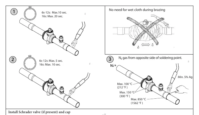
- Preparation: Remove the cap and access cap if present.
- Brazing: Use N2 gas from the opposite side of the soldering point. There is no need for a wet cloth during brazing.
- Temperature Limits: Ensure the soldering point does not exceed 850 °C (1562 °F). Keep the valve body temperature below 100 °C (212 °F) and the Schrader valve area below 150 °C (300 °F).
- Time Limits: Adhere to strict time limits based on valve size (e.g., 6s-12s valves: max 10 sec for step 1, max 5 sec for step 2).
Schrader Valve and Cap Installation
If a Schrader valve is present, install it with an approximate torque of 0.3 Nm / 0.2 ft-lbs. When tightening the cap, use the following torque specifications based on valve size:
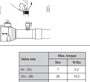
- 6s - 12s: 10 Nm / 7.4 ft-lbs
- 16s - 22s: 15 Nm / 11.0 ft-lbs
- 25s - 35s: 20 Nm / 14.8 ft-lbs
- 42s: 32 Nm / 23.6 ft-lbs
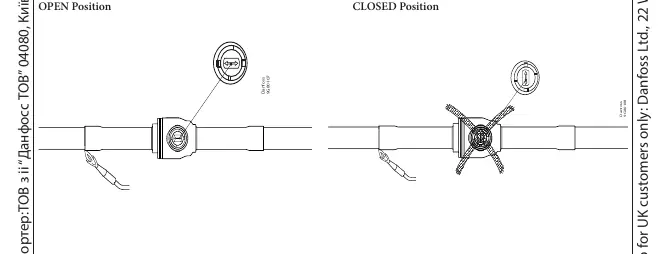
Operation
The valve can be set to fully open or fully closed positions. Ensure the valve is in the correct position for system maintenance or operation. The valve is fully open when the handle is parallel to the flow direction and fully closed when perpendicular.
Manufacturer information
Danfoss A/S
Practical help
Common problems
Excessive pressure build-up
Ensure only authorized personnel operate the valve and verify system design for R744 applications.
Valve damage during brazing
Use N2 gas from the opposite side of the soldering point and strictly observe the time limits and temperature maximums provided.
Before use
- Verify the refrigerant is R 744 (CO2).
- Ensure system pressure does not exceed 90 bar (1305 psig).
- Check that the operating temperature is within -40 °C to 100 °C.
- Ensure you have the correct torque wrench for cap installation.
- Confirm the valve size to apply the correct torque settings.
Specs in practice
- Max. working pressure
- The maximum pressure the valve can safely handle (90 bar).
Images and diagrams
- Brazing steps showing time limits and temperature zones.
- Torque tables for different valve sizes.
- Visual indicators for fully open and fully closed valve positions.
Model compatibility
- Designed specifically for R 744 (CO2) refrigerant systems.
- For secondary loop or cascade systems, consult the full datasheet.

Manual page author
David Miller
Documentation analyst
Organizes user manual content into clear summaries, with attention to model details, product context, and everyday usability.