HVAC / Thermostats & Controls
Installation Guide for Danfoss ECL Comfort 120
Quick installation and setup guide for the Danfoss ECL Comfort 120 electronic controller. Includes wiring diagrams, mounting instructions, technical specifications, and commissioning steps via the Leanheat Monitor app.
Table of contents
Manual images
Click an image to enlargeQuick guide from the manual
This document provides installation and commissioning instructions for the Danfoss ECL Comfort 120 electronic controller. It is intended for professional installers. The guide covers physical mounting, electrical wiring based on specific system configurations, and initial setup using the Leanheat Monitor application.
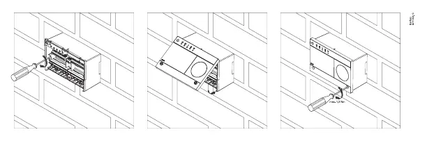
Mounting
The ECL Comfort 120 can be mounted on a wall or a DIN rail. Ensure the installation environment is suitable for electronic equipment. When mounting, ensure the device is securely fastened. Tighten terminal screws to a maximum torque of 1.2 Nm.
Wiring and Connections
The controller supports various system configurations. Refer to the specific wiring diagrams (A130.1 ex. a through A130.4) provided in the manual to match your system setup. Key connection points include:
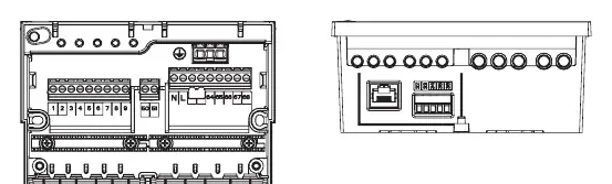
- Sensors (S1-S4): Inputs for temperature or other sensors.
- Pumps (P1): Output for pump control.
- Power Supply: 230 V a.c. connection.
- Communication: Ethernet and Modbus terminals (32-36).
- PWM: Pulse Width Modulation inputs and outputs.
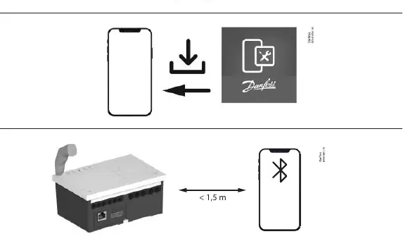
Commissioning
Commissioning is performed using the Leanheat Monitor application. Ensure your mobile device is within 1.5 meters of the controller during the pairing process. Follow the in-app instructions to complete the setup.
Technical Specifications
- Supply Voltage: 230 V a.c.
- Relay Load: 4 (2) A / 230 V a.c.
- PWM Output: 100-1000 Hz
- PWM Input: 30-100 Hz
- Power Consumption: 15 VA / 230 V a.c.
Manufacturer information
Danfoss A/S
Practical help
Common problems
Device not connecting during commissioning
Ensure the mobile device is within 1.5 meters of the controller and Bluetooth is enabled.
Incorrect system operation
Verify that the wiring matches the specific diagram (A130.1 to A130.4) corresponding to your system configuration.
Before use
- Verify the power supply is 230 V a.c.
- Ensure the mounting surface is stable for wall or DIN rail installation.
- Check that all electrical connections are secure and tightened to max 1.2 Nm.
- Download the Leanheat Monitor app for commissioning.
- Confirm the system configuration matches one of the provided wiring diagrams.
Specs in practice
- 4 (2) A / 230 V a.c.
- Maximum relay load capacity for connected devices.
- PWM out: 100-1000 Hz
- Frequency range for Pulse Width Modulation output signals.
- PWM in: 30-100 Hz
- Frequency range for Pulse Width Modulation input signals.
Images and diagrams
- A130.1 - A130.4: Wiring diagrams illustrating connections for different heating/cooling system configurations.
- Terminal block diagram: Shows the layout for sensors, pumps, power, and communication ports.
Model compatibility
- Compatible with Leanheat Monitor software.
- Designed for 230 V a.c. power supply systems.

Manual page author
David Miller
Documentation analyst
Organizes user manual content into clear summaries, with attention to model details, product context, and everyday usability.