HVAC / Thermostats & Controls
Installation Guide for Danfoss Icon Expansion Module
Quick installation and configuration guide for the Danfoss Icon Expansion Module. Learn how to wire the module, select applications (0001-0011), configure settings, and perform system tests.
Table of contents
Manual images
Click an image to enlargeQuick Guide from the Manual
The Danfoss Icon Expansion Module is designed to be inserted into the Danfoss Icon Master Controller to provide additional features for various heating and cooling applications. This guide covers the installation, application selection, and testing procedures required to set up the system.
Installation and Wiring
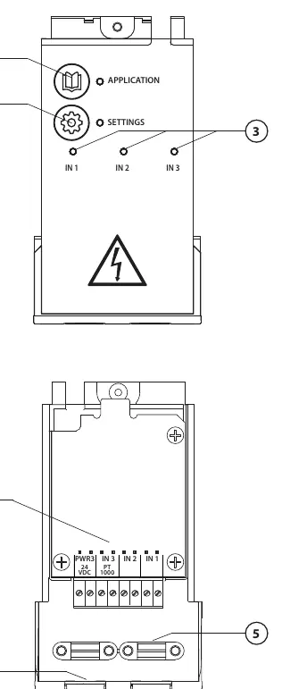
Perform all wiring according to the specific electrical diagram for your chosen application before inserting the Expansion Module into the Danfoss Icon Master Controller. The module features terminals for inputs (IN 1-3), a PT1000 sensor connection, and 24V power. Ensure proper cable strain relief is used.
Application Selection
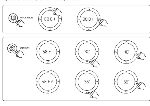
The module supports 11 different applications (0001-0011). To select an application:
- Press the Application key.
- Use the up and down arrows to select the desired application number (1-11).
- Confirm your selection by pressing OK.
Application Settings
Once an application is selected, use the Settings key to configure parameters specific to that application. Settings typically include supply flow temperatures, safety cut-off temperatures, cooling hysteresis, and neutral times. Refer to the specific application section in the manual for the exact parameters available for your configuration.
Application Test Function
The Application test (APP test) ensures all components are installed correctly. To perform the test:
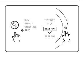
- Enter the Test menu via the installer key.
- Select TEST APP and confirm with OK.
- Follow the specific steps displayed on the Master Controller. The test will cycle through outputs (e.g., heating mode, cooling mode, neutral mode) to verify that valves and actuators respond correctly.
Thermostat Settings
For cooling applications, you can exclude specific rooms (e.g., bathrooms) from cooling by adjusting the thermostat menu settings. You can also assign a reference room thermostat to control the system's transition between heating and cooling modes based on the actual room temperature.
Global Standby
The Global standby is a potential-free input that allows you to remotely set the system to 'away' mode (15°C setpoint), for example, via an external GSM module.
Manufacturer information
Danfoss A/S
Practical help
Common problems
Valve not opening during test
Check wiring and ensure the test period (up to 3 minutes) has elapsed.
Cooling not activating
Ensure the dew point sensor is installed and active, and that the room thermostat is enabled for cooling.
System not switching to cooling
Check if the reference room thermostat is correctly assigned and the neutral time has passed.
Before use
- Ensure the Danfoss Icon Master Controller is powered off before installation.
- Verify all components (valves, actuators, sensors) match the parts list for your chosen application.
- Check that the wiring matches the specific electrical diagram for the application.
- Ensure the dew point sensor is installed for cooling applications to prevent condensation.
Specs in practice
- Global Standby
- A potential-free input to remotely set the system to 'away' mode (15°C setpoint).
Images and diagrams
- The module features terminals for inputs (IN 1-3), a PT1000 sensor connection, and 24V power.
- The interface includes an Application key for selecting modes 1-11 and a Settings key for configuration.
Model compatibility
- Requires Danfoss Icon Master Controller.
- Compatible with various actuators (TWA-A, ABN-FBH) and sensors (ESM-11 PT1000, CF-DS dew point sensor).

Manual page author
David Miller
Documentation analyst
Organizes user manual content into clear summaries, with attention to model details, product context, and everyday usability.