HVAC / Thermostats & Controls
Danfoss Icon Display 24V Room Thermostat Installation Guide
A comprehensive installation and configuration guide for the Danfoss Icon Display 24V room thermostat. Includes step-by-step mounting instructions, wiring diagrams, and details on accessing the installer menu to configure temperature...
Table of contents
Manual images
Click an image to enlargeQuick Guide from the Manual
This document provides installation and configuration instructions for the Danfoss Icon Display 24V room thermostat. The thermostat supports both bus and star wiring configurations. If a floor sensor is used, it must be installed in a conduit (gooseneck) for protection.
Installation and Demounting
Follow the steps below to install or remove the thermostat:
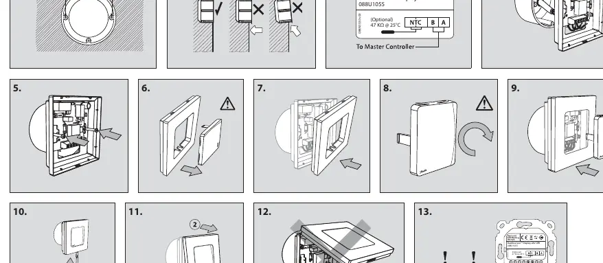

- Installation: Follow steps 1 through 9 to mount the thermostat to the wall.
- Demounting: Follow steps 10 through 12 to remove the thermostat from the wall.
- Wiring: Ensure the floor sensor is placed in a conduit as shown in step 13.
Installer Menu
To access the installer menu, follow these steps:
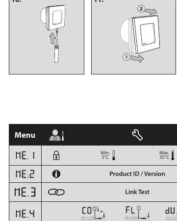
- Press and hold the button to open the Settings menu.
- Press and hold the button again while in the Settings menu to enter the Installer Menu.
Menu Options
- ME.1: Room temperature range limits.
- ME.2: Product ID and version information.
- ME.3: Link test to the main controller. Returns a percentage (0-100%); 80% or higher indicates a strong connection.
- ME.4: Floor sensor mode:
- Comfort mode: Uses both room and floor sensors.
- Floor mode: User sets the desired floor temperature.
- Dual mode: Controls radiators and floor heating circuits.
- ME.5: Min. and max. floor temperature settings for modes in ME.4.
- ME.6: Reference room setting. Enable (ON) if this thermostat should act as the reference for switching between heating and cooling.
- ME.7: Cooling ON/OFF. Used to disable cooling (e.g., in bathrooms).
Manufacturer information
Danfoss A/S
Practical help
Common problems
Weak connection to main controller
Perform a Link Test (ME.3). A value of 80% or higher is required for a strong connection.
Floor sensor not functioning
Ensure the floor sensor is installed inside a conduit (gooseneck) as specified in the installation diagram.
Before use
- Verify the wiring configuration (bus or star).
- Ensure the floor sensor is installed in a conduit if applicable.
- Access the Installer Menu (ME.4) to configure the correct floor sensor mode.
- Check the Link Test (ME.3) to ensure communication with the main controller.
Specs in practice
- ME.3 Link Test
- Tests the connection quality to the main controller. 0-100% scale; 80% or higher is recommended.
- ME.4 Floor Sensor Mode
- Determines how the thermostat utilizes the floor sensor (Comfort, Floor, or Dual mode).
- ME.6 Reference Room
- When ON, this thermostat acts as the reference for heating/cooling switching.
Images and diagrams
- Steps 1-9: Mounting procedure for the thermostat.
- Steps 10-12: Demounting procedure.
- Step 13: Wiring diagram showing the floor sensor installation in a conduit.
Model compatibility
- Compatible with bus or star wiring configurations.
- Optional floor sensor requires a 47 kΩ @ 25°C specification.

Manual page author
Michael Turner
Technical manual editor
Reviews PDF manuals for structure, safety notes, and practical product details so readers can find the right information quickly.