HVAC / Thermostats & Controls
User Guide for Danfoss Icon 2 Main Controller
Quick guide for the Danfoss Icon 2 Main Controller (088R0400). Includes wiring diagrams, technical specifications, and installation instructions for the heating control system.
Table of contents
Quick Guide
The Danfoss Icon 2 Main Controller is designed for individual electronic room temperature control. Before installation or maintenance, always disconnect the power supply to ensure safety. The system supports up to 15 thermostats and 15 actuators. Ensure all wiring is performed by qualified personnel according to local regulations.
Technical Specifications
- Max number of thermostats: 15
- Max number of actuators: 15
- Internal fuse: 2 A
- Mains Power: 220-240 V (50/60 Hz)
- Boiler Relay: Voltage free, max 2 A, max 230 V
- Input 1 & 2: Voltage free (Setback / Cooling)
- Storage Temperature: -20 °C to +60 °C
- Protection Class: Class II with earthing terminal
- Control Action Type: 1 b
Wiring and Installation
The controller features a terminal block for easy connection. Use the 'push to release' mechanism to insert or remove cables. Ensure that cable cross-sections are less than 1.5 mm². For 24V actuators, an optional conversion module (088U2140) is required.
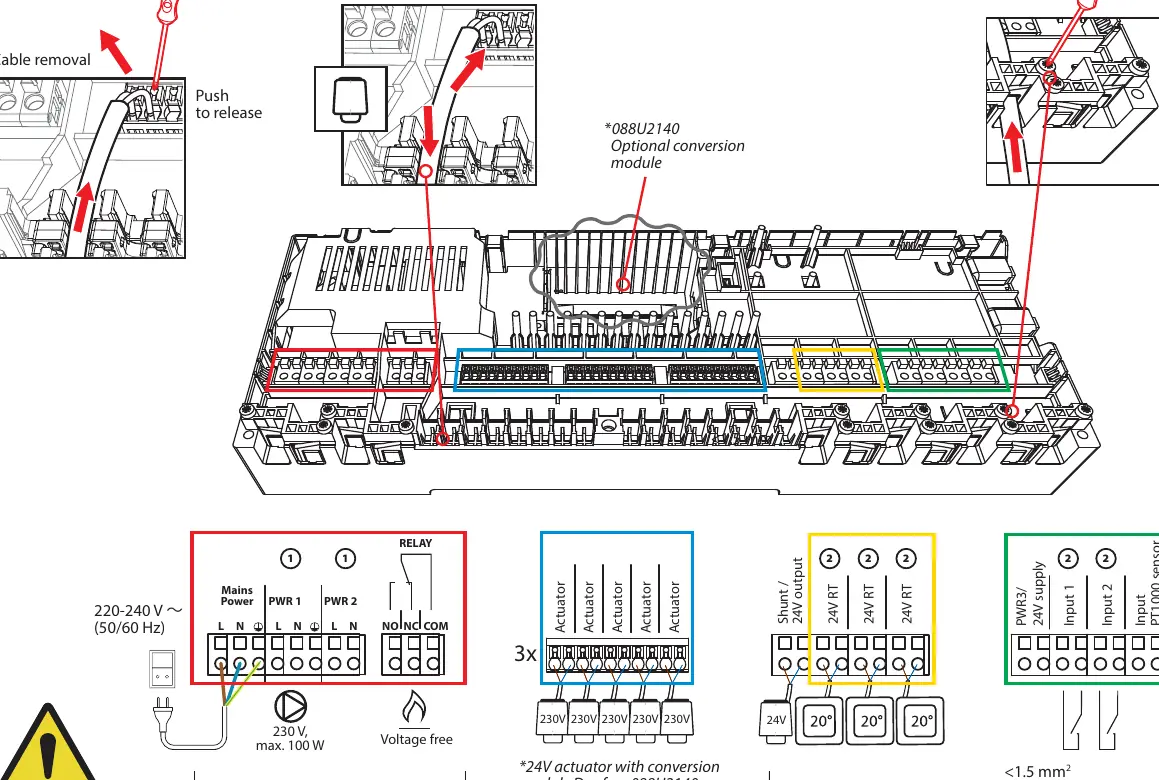
Wiring connections include:
- Mains Power: L and N terminals.
- Relay: NO, NC, and COM terminals for boiler control.
- Actuators: Dedicated terminals for up to 15 actuators.
- Inputs: Terminals for Input 1, Input 2, and PT1000 sensor.
Compliance
The Danfoss Icon 2 MC complies with LVD, EMC, RoHS, WEEE, and RED directives. The full text of the EU declaration of conformity is available at heating.danfoss.com.
Official resources from the manual
Manufacturer information
Danfoss A/S
Practical help
Common problems
Device does not power on
Check the mains power connection and verify the internal 2 A fuse is intact.
Actuators not responding
Verify wiring connections and ensure the total number of connected actuators does not exceed 15.
Boiler not triggering
Ensure the relay is wired correctly to the NO/NC/COM terminals and that the boiler control logic is configured.
Before use
- Disconnect power before opening the controller housing.
- Ensure all cables are less than 1.5 mm².
- Verify mains voltage is 220-240 V (50/60 Hz).
- Check that the relay load does not exceed 2 A.
- Use the optional conversion module (088U2140) if using 24V actuators.
Specs in practice
- Voltage free relay
- The relay output acts as a switch and does not provide power to the connected boiler.
- Internal fuse: 2 A
- Protects the controller's internal electronics from overcurrent.
Images and diagrams
- The wiring diagram illustrates the connection points for Mains Power, Relay, Actuators, and Inputs.
- The cable installation diagram shows the 'push to release' mechanism for secure wire termination.
Model compatibility
- Compatible with 24V actuators only when using the optional conversion module (088U2140).

Manual page author
Michael Turner
Technical manual editor
Reviews PDF manuals for structure, safety notes, and practical product details so readers can find the right information quickly.