Industrial / Valves
Installation Guide for Danfoss CTR 20 Electric 3-Way Valve
Quick installation and service guide for the Danfoss CTR 20 electric 3-way valve. Includes technical specifications, brazing and welding instructions, electrical connection details, and maintenance procedures.
Table of contents
Manual images
Click an image to enlargeQuick guide from the manual
The Danfoss CTR 20 is an electric 3-way valve designed primarily for heat reclaim applications. The valve is delivered in a half-opened position, which is the required state for brazing and welding. Important: Do not disassemble the valve before brazing or welding. Always connect the valve to an appropriate controller or driver; never connect it directly to an AC/DC power source. Do not operate the valve while assembling or disassembling.
Technical specifications
- Stepper motor type: Bipolar
- Refrigerant: R744 (contact Danfoss for other refrigerants)
- Max working pressure: 140 Bar / 2030 psig
- Ambient temperature: -40 °C to 60 °C (-40 °F to 140 °F)
- Fluid temperature: 0 °C to 150 °C (32 °F to 302 °F)
- Phase Current: 100 mA RMS / 141 mA Peak
- Coil resistance: 52 Ohm ±10% (at 25 °C)
- Total full steps: 6600
- Step rate: 75 stp./sec.
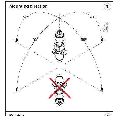
Installation and mounting
The valve can be installed in various orientations. When brazing or welding, ensure the valve remains in the middle position as delivered. The maximum temperature at the valve body during brazing must not exceed 75 °C (167 °F).
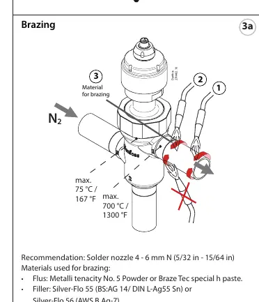
Brazing
- Use solder nozzle 4 - 6 mm (5/32 in - 15/64 in).
- Recommended materials: Metalli tenacity No. 5 Powder or Braze Tec special h paste (flux); Silver-Flo 55 or Silver-Flo 56 (filler).
- Warning: Do not use filler metals containing Phosphor (e.g., BS: CP 1/DIN L-Ag 15P or BS: CP 3/DIN L-Ag P7).
Welding
- Recommended for TIG welding: Power approximately 60A.
- Use Argon shield gas charge.
- Material for welding: Approximately 2 mm thick stainless steel alloy.
Electrical connections
The valve uses an M12 connection. The pin configuration is as follows:
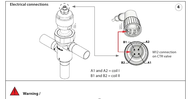
- A1 and A2: Coil I
- B1 and B2: Coil II
Service and maintenance
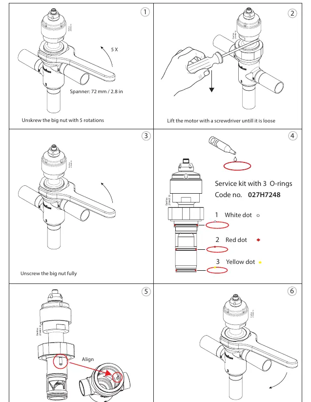
Service should only be performed by qualified personnel. A service kit (Code no. 027H7248) is available, containing 3 O-rings. When replacing O-rings, ensure the "fixing" pin is correctly aligned in the gap. The maximum torque for the big nut is 130 Nm (95.9 ft-lbf).
Manufacturer information
Danfoss A/S
Practical help
Common problems
Valve does not operate
Ensure the valve is connected to an appropriate controller/driver and not directly to an AC/DC power source.
Brazing/Welding damage
Ensure the valve body temperature does not exceed 75 °C (167 °F) during the process. Do not disassemble the valve before brazing.
Incorrect electrical connection
Verify wiring: A1/A2 for Coil I and B1/B2 for Coil II on the M12 connector.
Before use
- Verify the refrigerant is R744.
- Ensure the valve is in the middle position (as delivered).
- Check that the controller/driver is compatible with bipolar stepper motors.
- Verify brazing/welding equipment is set to appropriate temperature limits.
- Ensure the fixing pin is aligned during any service reassembly.
Specs in practice
- Bipolar stepper motor
- Requires a specific controller/driver to operate; cannot be powered directly by AC/DC mains.
- 140 Bar max pressure
- The maximum operating pressure the valve can withstand.
- 6600 total steps
- The total range of motion for the valve actuator.
Images and diagrams
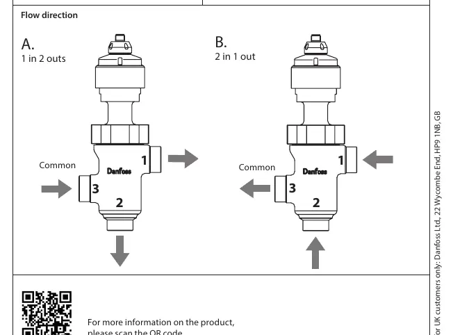
- Flow direction A: 1 in, 2 outs.
- Flow direction B: 2 in, 1 out.
- M12 connection pinout: A1, A2, B1, B2.
Model compatibility
- Designed for R744 refrigerant.
- Contact Danfoss for compatibility with other refrigerants.
- Requires specific controller/driver for operation.

Manual page author
Michael Turner
Technical manual editor
Reviews PDF manuals for structure, safety notes, and practical product details so readers can find the right information quickly.