Industrial / Electrical
Danfoss 027F3384 Overhaul Kit Installation Guide
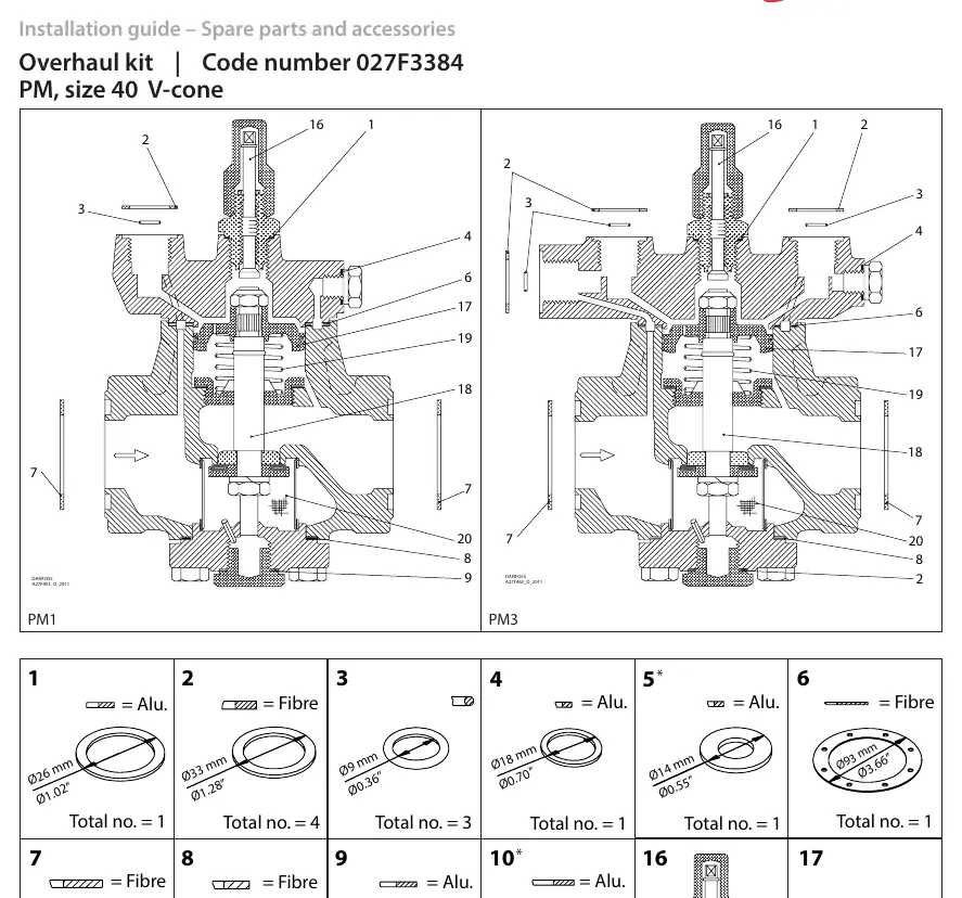
Quick guide for the Danfoss 027F3384 Overhaul Kit for PM size 40 V-cone valves. Includes exploded view diagrams for PM1 and PM3 valves and a detailed spare parts list with specifications.
Table of contents
Quick guide from the manual
This document serves as an installation and parts reference guide for the Danfoss 027F3384 Overhaul Kit, specifically designed for PM size 40 V-cone valves. It provides exploded view diagrams for PM1 and PM3 valve configurations and a detailed list of included spare parts to assist with maintenance and repair.
Valve Assembly Diagrams
The manual provides exploded view diagrams for two valve configurations: PM1 and PM3. These diagrams illustrate the correct placement of internal components, including seals, springs, and valve cones, identified by reference numbers 1 through 20. Use these diagrams to identify the correct location of each component during assembly.
Spare Parts Identification
The kit includes various components made of Aluminum (Alu.) or Fibre. Each part is identified by a reference number corresponding to the assembly diagrams. Key specifications provided for each part include:
- Reference Number: Corresponds to the diagram labels.
- Material: Indicates whether the part is Aluminum or Fibre.
- Dimensions: Provided in both millimeters (mm) and inches (").
- Quantity: Specifies the total number of each part included in the kit.
Important Notes
Please note that some spare parts included in the package may not be used for specific configurations, such as PM 1 or PM 3 with V-cone. Always verify the assembly requirements against the provided diagrams before installation to ensure all necessary parts are correctly positioned.
Manufacturer information
Danfoss A/S
Practical help
Common problems
Unused parts in the kit
Some parts are included in the package but are not required for PM 1 or PM 3 with V-cone configurations. Refer to the diagrams to confirm which parts are necessary for your specific valve model.
Before use
- Confirm the valve model is PM size 40 V-cone.
- Identify the valve configuration (PM1 or PM3).
- Cross-reference parts with the exploded diagram using the reference numbers.
- Check material types (Alu. vs Fibre) for correct placement.
Specs in practice
- Reference Number
- Identifier used to locate the part in the exploded assembly diagram.
Images and diagrams
- Exploded view of PM1 valve assembly showing component placement.
- Exploded view of PM3 valve assembly showing component placement.
Model compatibility
- Designed specifically for PM size 40 V-cone valves.
- Some parts are not used for PM 1 or PM 3 with V-cone configurations.

Manual page author
Michael Turner
Technical manual editor
Reviews PDF manuals for structure, safety notes, and practical product details so readers can find the right information quickly.