HVAC / Refrigeration Components
Installation Guide for Danfoss Sight Glass LLG
Official installation and maintenance guide for the Danfoss Sight Glass LLG. Includes mounting instructions, torque specifications for 12 and 20-screw configurations, and packing replacement procedures.
Table of contents
Manual images
Click an image to enlargeImportant Information
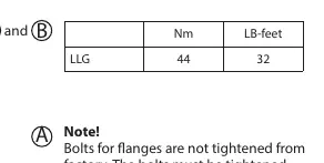
Note: Bolts for flanges are not tightened from the factory. The bolts must be tightened on site according to the specified torque values. Always ensure there is sufficient space behind the LLG for proper insulation and service inspection.
Installation
Install the LLG 185-1550 on a bracket using the 4 screws delivered with the glass. Use the threaded holes on the back of the frame to mount the glass on the bracket (bracket not supplied by Danfoss).
Piping Connection: Always connect the piping after mounting the LLG on the bracket. It is critical to ensure a minimum of stress in the liquid level glasses from the connected pipes.
Maintenance and Packing Replacement
To replace the packing, follow these steps:
- Loosen all LLG screws by 1/4 of a turn in reverse order of the tightening sequence. Loosen all screws completely in the same order.
- Remove all remains of old packing material and clean all surfaces. Ensure there are no burrs, marks, or scratches on the surface.
- Unpack the new packing, ensuring it is kept clean and is not damaged (bent or scratched).
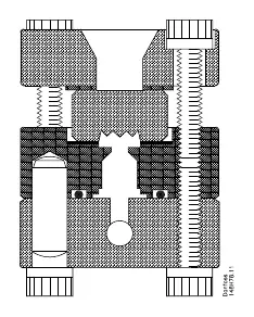
- Place the packing on the packing surface of the back piece and mount the glass on top. Place the protection plate on the glass and mount the front piece on top. (For LLG SF, the sight adapter serves as the protection plate).
- Tighten the screws following the specific sequence (see diagrams).
Tightening Torque
Tighten the screws according to the following steps:
- Point 1: Tighten the screws by hand until they touch the front piece.
- Point 2: Use a torque wrench to tighten the screws to 15 Nm (11 ft-lb).
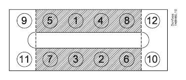
- Point 3 (12 screws): Tighten screws 1-8 to 30 Nm (22 ft-lb) and screws 9-12 to 15 Nm (11 ft-lb).
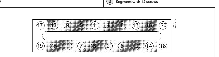
- Point 3 (20 screws): Tighten screws 1-16 to 30 Nm (22 ft-lb) and screws 17-20 to 15 Nm (11 ft-lb).
- Repeat Point 3 until none of the screws can be turned at the stated moments.
Technical Specifications
Max. Operating Pressure: 25 bar g (362 psi g).
Working Temperature:
- LLG, LLG S: -10°C to +100°C (+14°F to +212°F).
- LLG SF (with sight adapter): -50°C to +30°C (-58°F to +86°F).
Manufacturer information
Danfoss A/S
Practical help
Common problems
Bolts are loose upon delivery
Bolts for flanges are not tightened from the factory; they must be tightened on site using a torque wrench.
Internal stress in the glass
Always connect piping only after the LLG is mounted on the bracket to minimize stress.
Packing leaks or damage
Ensure all surfaces are clean and free of burrs, marks, or scratches before installing new packing.
Before use
- Verify the mounting bracket is ready (not supplied by Danfoss).
- Ensure sufficient space is available behind the LLG for insulation and service.
- Have a torque wrench available for installation.
- Check that the packing is clean and undamaged before installation.
Specs in practice
- Max. Operating Pressure
- 25 bar g (362 psi g).
- LLG/LLG S Temperature
- -10°C to +100°C (+14°F to +212°F).
- LLG SF Temperature
- -50°C to +30°C (-58°F to +86°F).
Images and diagrams
- Figure 1: Cross-section showing the assembly order of the back piece, packing, glass, protection plate, and front piece.
- Figure 2: Tightening sequence for the 12-screw configuration.
- Figure 3: Tightening sequence for the 20-screw configuration.
Model compatibility
- The LLG SF model includes a sight adapter that also functions as a protection plate.

Manual page author
Emily Carter
User documentation editor
Prepares concise manual descriptions and highlights the most useful setup, operation, and maintenance information for readers.