General / Other Manuals
Operating Guide for Danfoss AME 140X Actuator
Quick guide for the Danfoss AME 140X actuator. Includes installation steps, wiring diagrams, DIP switch settings, manual override procedures, and LED status indicators.
Table of contents
Manual images
Click an image to enlargeQuick guide from the manual
The Danfoss AME 140X is an actuator designed for modulating control. This guide covers essential installation, configuration, and maintenance procedures. Safety Warning: Necessary assembly, start-up, and maintenance must be performed by qualified personnel only. Always switch off the power supply before removing the cover. The device requires a 24V AC power supply connected via a safety isolating transformer.
Mounting and Installation
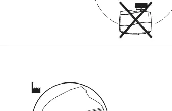
The actuator should be mounted with the valve stem in either a horizontal position or pointing upwards.
- Valve Check: Inspect the valve neck before installation.
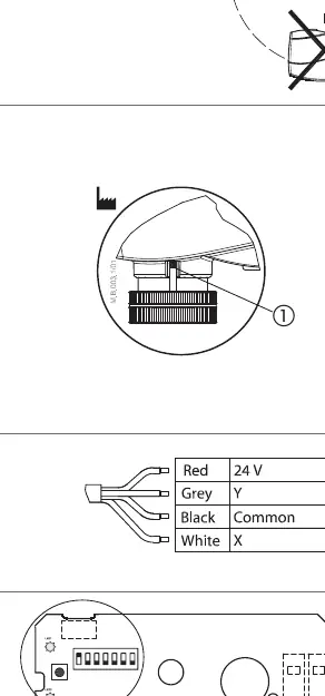
- Positioning: Ensure the actuator is in the 'steam up' position (factory setting) before mounting.
- Securing: Mount the actuator securely on the valve body using the ribbed nut. Tighten by hand; no tools are required.
- Wiring: Connect the actuator according to the provided wiring diagram.
DIP Switch Settings
The actuator features 7 DIP switches for configuration. Factory settings have all switches in the OFF position, except SW 1 which is ON.
- SW 1 (Input signal range): OFF for 2-10V/4-20mA; ON for 0-10V/0-20mA.
- SW 2 (Direct/Inverse): OFF for direct acting; ON for inverse acting.
- SW 3 (Normal/Sequential): OFF for normal; ON for sequential mode.
- SW 4 (Sequential range): OFF for 0-5V/0-10mA; ON for 5-10V/10-20mA.
- SW 5 (Flow characteristic): ON for linear to modified flow (VZL valves); OFF for standard.
- SW 6 (Anti-blocking): ON to enable valve motion every 7 days; OFF to disable.
- SW 7 (Input type): OFF for voltage input; ON for current input.
Manual Override
Warning: Do not manually operate the drive if power is connected. Do not dismount the actuator from the valve if it is in a stem-down position, as this risks the actuator getting stuck.
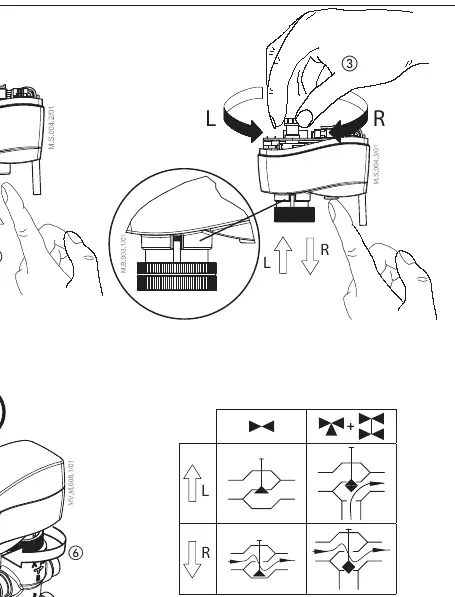
- Remove the cover.
- Press and hold the button on the bottom side of the actuator during manual override.
- Replace the cover after adjustment.
- Install the actuator back on the valve.
A 'click' sound after energizing indicates the gear wheel has returned to the normal position.
LED Signalization
The LED provides status feedback:
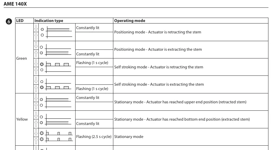
- Green (Constantly lit): Positioning mode (retracting or extracting stem).
- Green (Flashing 1s): Self-stroking mode.
- Yellow (Constantly lit): Stationary mode (reached end position).
- Yellow (Flashing 2.5s): Stationary mode.
- Red (Flashing 1s): Error mode.
- Dark: No power supply.
Manufacturer information
Danfoss A/S
Practical help
Common problems
Actuator gets stuck
Ensure the actuator was not dismounted while in a stem-down position.
Error Mode (Red LED flashing)
Check wiring and power supply; perform a reset by pressing the reset button for 2 seconds.
No LED indication
Verify that the power supply is connected and active (24V AC).
Before use
- Verify power supply is 24V AC via safety isolating transformer.
- Check valve neck for compatibility.
- Ensure actuator is in 'steam up' position (factory setting).
- Verify wiring against the diagram.
- Ensure the ribbed nut is tightened by hand.
Images and diagrams
- Wiring diagram shows connections for 24V power and signal inputs (Red, Grey, Black, White).
- DIP switch diagram illustrates the ON/OFF positions for configuration.
Model compatibility
- Compatible with VZ and VZL valve series.
- Requires 24V AC power supply.

Manual page author
Emily Carter
User documentation editor
Prepares concise manual descriptions and highlights the most useful setup, operation, and maintenance information for readers.