Hvac / Air Conditioners
Installation Guide for Danfoss Solenoid Coil Types BB, BG, BQ, BT, BU, BY and BN
A comprehensive installation guide for Danfoss Solenoid Coils (Types BB, BG, BQ, BT, BU, BY, and BN). This guide covers technical specifications, wiring diagrams, torque settings, and safety instructions for proper installation and...
Table of contents
Quick guide from the manual
This document provides installation and technical data for Danfoss Solenoid Coils, including types BB, BG, BQ, BT, BU, BY, and BN. The coils are categorized by their connection type:
- Type A: Spade connection (IP00/PD3)
- Type B: Cable plug (IP65/PD3 or IP67/PD4)
- Type C: Terminal box (IP67/PD4)
- Type D: Moulded cable (IP67/PD4)
Safety information
To ensure safe operation and compliance with standards, observe the following requirements:
- Only qualified personnel are permitted to install or maintain this product.
- Always disconnect the power supply before dismounting the coil.
- Avoid direct exposure to alkaline conditions; use in neutral conditions is recommended.
- If the coil is used as an independently mounted control, the end-user must use a plastic cable gland with strain relief.
- Technical specifications are according to EN60730-1.
Installation and assembly
Installation procedures vary based on the coil type. Refer to the specific diagrams for your model:
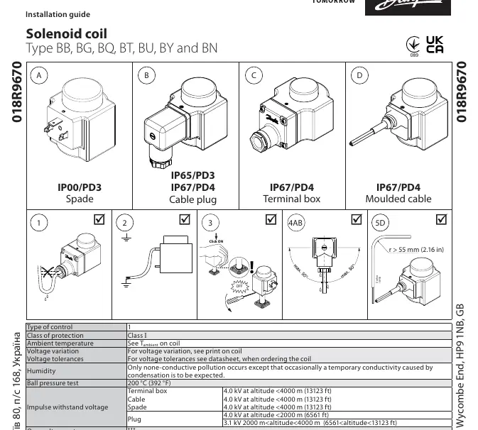
- General Installation: Ensure the cable radius is greater than 55 mm (2.16 in).
- Type B (Cable Plug): Follow the assembly sequence shown in the diagrams, ensuring proper torque application (e.g., 40-50 Ncm for cable gland, 250-375 Ncm for housing).
- Type C (Terminal Box): Follow the assembly sequence, ensuring proper torque application (e.g., 40-50 Ncm for cable gland, 320-370 Ncm for housing).
- Plugs: Plugs can be removed and mounted a maximum of 10 times.
Technical specifications
Key operational parameters for the solenoid coils:
- Class of protection: Class I
- Overvoltage category: III
- Ball pressure test: 200 °C (392 °F)
- Humidity: Only non-conductive pollution occurs, except for temporary conductivity caused by condensation.
- Impulse withstand voltage: 4.0 kV (at altitude
- Surface temperature: Independently mounted controls should be sealed if the coil temperature exceeds 85°C.
Maintenance and disposal
The supply cord of the moulded cable control cannot be replaced. If the cord is damaged, the entire control must be discarded. Ensure all connections are secure and comply with the specified torque values to maintain the IP rating.
Manufacturer information
Danfoss A/S
Practical help
Common problems
Damaged supply cord on moulded cable
The cord cannot be replaced; the control must be discarded.
Coil temperature exceeds 85°C
Independently mounted controls must be sealed.
Cable gland requirements
Use a plastic cable gland with strain relief if the coil is used as an independently mounted control.
Before use
- Verify the coil type (BB, BG, BQ, BT, BU, BY, or BN).
- Ensure power is disconnected before starting installation.
- Check that the environment is non-alkaline.
- Confirm cable size matches terminal box requirements (0.75 - 1.5 mm²).
- Verify altitude requirements for impulse withstand voltage.
Specs in practice
- Impulse withstand voltage
- Maximum voltage surge the coil can handle based on altitude.
- Torque values
- Specific tightening force required for assembly (e.g., 40-50 Ncm).
Images and diagrams
- Type A (Spade): IP00/PD3 protection.
- Type B (Cable plug): IP65/PD3 or IP67/PD4 protection.
- Type C (Terminal box): IP67/PD4 protection.
- Type D (Moulded cable): IP67/PD4 protection.
Model compatibility
- Plugs can be removed/mounted a maximum of 10 times.
- Technical specifications comply with EN60730-1.

Manual page author
David Miller
Documentation analyst
Organizes user manual content into clear summaries, with attention to model details, product context, and everyday usability.