Industrial / Pumps Motors
Danfoss BFPH Fuel Unit Instructions
Quick guide for the Danfoss BFPH fuel unit. Includes installation instructions, connection diagrams, pressure settings, air bleeding procedures, and safety precautions for one-pipe and two-pipe systems.
Table of contents
Manual images
Jump to the sectionQuick guide from the manual
The Danfoss BFPH fuel unit is designed for oil burner systems. Key operational requirements include ensuring the inlet/return pressure does not exceed 30 psi and using a quality filter in the supply line. Bleeding is only required for 1-pipe systems, as 2-pipe systems bleed automatically. Always ensure the unit is mounted correctly to avoid shaft seal damage.
Technical Data
The unit is compatible with Fuel #2 or lighter fuel up to B10. Factory pressure setting is 100 psi.
- Pressure with Fuel #2: 100-160 psi (1725 rpm) or 100-210 psi (3450 rpm).
- Pressure with Lighter Fuel: 100-210 psi (3450 rpm) or 100 psi (1725 rpm).
- Strainer capacity: 3 gal/h.
Connections
The fuel unit ports are designated as follows:
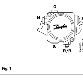
- N (Nozzle port): 1/8" NPTF
- G (Pressure gage port): 1/8" NPTF
- S (Suction port/vacuum gage port): 1/4" NPTF
- R/B (Return port/bleed port): 1/4" NPTF
Installation and Mounting
Proper mounting is critical for the longevity of the unit:
- Avoid mounting with the shaft pointing upwards.
- Avoid mounting with the nozzle outlet pointing upwards in 1-pipe systems with lift.
- Use non-hardening oil pipe dope for all thread connections; avoid Teflon tape as pieces can cause blockages.
Air Bleeding
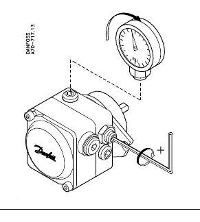
Air bleeding is only necessary for 1-pipe systems. To bleed, open the bleeder screw a maximum of 1/2 turn. In 2-pipe systems, the unit bleeds automatically through the return line.
System Configurations
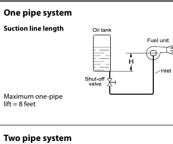
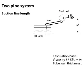
The BFPH unit supports both one-pipe and two-pipe installations. The maximum one-pipe lift is 8 feet. For two-pipe systems, ensure the suction line length is calculated based on the pump size and lift height as specified in the technical tables.
Safety and Maintenance
The unit features a high-pressure relief function. If activated, it indicates a system problem such as thermal expansion of oil or supply pressure set too high. Check for water contamination, check valves, or other restrictions in the lines. Do not use check valves or equivalent components in oil lines that restrict oil flow back to the supply tank unless a pressure relief means is installed.
Spare Parts
- Strainer: 071N1392
- O-ring for cover sealing: 633B0090
- Bleed plug: 071N1011
Manufacturer information
Danfoss A/S
Practical help
Common problems
High pressure relief function activated
Check for water contamination, check valves, or supply pressure settings. Ensure outdoor piping is insulated.
Air in the system
Bleed the system (only necessary for 1-pipe systems). Open bleeder max 1/2 turn.
Shaft seal damage
Ensure inlet/return pressure does not exceed 30 psi and avoid using Teflon tape on threads.
Before use
- Verify fuel type is Fuel #2 or lighter (up to B10).
- Ensure a quality filter is installed in the supply line.
- Check that the installation complies with National and Local Codes.
- Confirm mounting orientation (avoid shaft pointing upwards).
- Check that no check valves are restricting oil flow back to the tank.
Specs in practice
- N (Nozzle port)
- 1/8" NPTF connection for the nozzle line.
- G (Pressure gage port)
- 1/8" NPTF connection for monitoring pressure.
- S (Suction port)
- 1/4" NPTF connection for suction/vacuum gage.
- R/B (Return port)
- 1/4" NPTF connection for return line or bleeding.
Images and diagrams
- Fig 1: Port identification and connection layout.
- Fig 2: Air bleeding procedure using the bleeder screw.
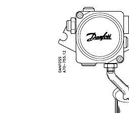
- Fig 3: Pressure adjustment and strainer maintenance.
Model compatibility
- Compatible with 1-pipe and 2-pipe installations.
- Maximum one-pipe lift is 8 feet.
- High pressure relief function included on units produced after June 17th, 2002 (date code 252).

Manual page author
Michael Turner
Technical manual editor
Reviews PDF manuals for structure, safety notes, and practical product details so readers can find the right information quickly.