Industrial / Pumps Motors
Installation Guide for Danfoss BFPW Fuel Unit
Quick installation and setup guide for the Danfoss BFPW fuel unit. Includes connection diagrams, pressure adjustment procedures, air bleeding instructions, and technical specifications.
Table of contents
Manual images
Jump to the sectionQuick guide from the manual
The Danfoss BFPW fuel unit is designed for use with used oil, No. 4, and lighter fuels. This guide covers the essential installation, connection, and maintenance procedures. Note that the pump does not feature an internal strainer, so an external filter in the supply line is mandatory for operation.
Installation
The fuel unit must be installed in accordance with the National Board of Fire Underwriters requirements and all applicable local ordinances. Ensure the suction line length is appropriate for the line size used:
- 1/2 inch ID: Maximum total length (horizontal and vertical) is 35 feet.
- 3/4 inch ID: Maximum total length (horizontal and vertical) is 45 feet.
Calculation basis: 460 SSU (100 cSt) corresponding to no. 4 fuel at 40°F.
Connections
Refer to the connection diagram for the following ports:
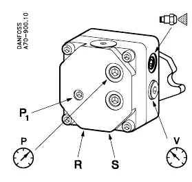
- P1: Pressure regulation.
- S: Suction line (1/4 NPTF).
- R: Return line (1/4 NPTF).
- Nozzle connection: Located on the left (1/4 NPTF).
- Pressure gauge connection & bleeding: G 1/8.
- Vacuum gauge connection: 1/8 NPTF.
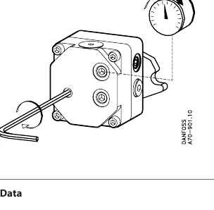
Pressure Adjustment
The pump pressure can be adjusted to meet system requirements. Ensure the pressure is set within the operating range of 80-210 psi. The factory setting is 60 psi.
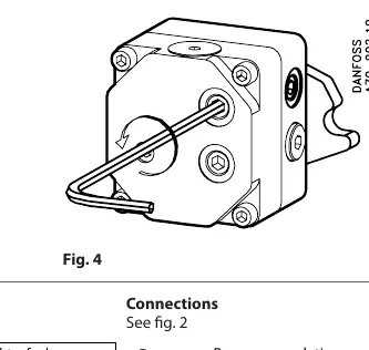
Air Bleeding
If the system requires air removal, the pump can be bled through the pressure gauge port located in the front or through the return port R.
Technical Data
- Oil types: Used oil, No. 4 & lighter fuels.
- Speed: Max. 3450 rpm.
- Pressure range: 80-210 psi.
- Factory setting: 60 psi.
- Maximum pressure on suction port: 30 psi.
- Transfer flow rating: 3 GPH.
- Operating vacuum (Used oil and no. 4 fuel): 20 in. HG.
- Operating vacuum (No. 2 and lighter fuel): 10 in. HG.
Manufacturer information
Danfoss A/S
Practical help
Common problems
Air in the fuel system
Perform air bleeding through the pressure gauge port in the front or through the return port R.
Debris or contaminants in fuel
Install an external filter in the supply line, as the pump does not have an internal strainer.
Before use
- Verify installation complies with National Board of Fire Underwriters requirements.
- Check local ordinances for specific installation rules.
- Ensure an external filter is installed in the supply line.
- Confirm the fuel type is compatible (Used oil, No. 4 & lighter).
- Check that the suction line diameter and length are within specified limits.
Specs in practice
- Transfer flow rating
- The pump capacity is 3 GPH.
- Operating vacuum
- Maximum vacuum allowed is 20 in. HG for heavier fuels and 10 in. HG for lighter fuels.
Images and diagrams
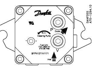
- Fig 1: Overview of the fuel unit and port locations.
- Fig 2: Detailed connection points for suction, return, nozzle, and gauges.
- Fig 3: Procedure for adjusting the pump pressure.
- Fig 4: Procedure for bleeding air from the system.
Model compatibility
- Compatible with used oil, No. 4, and lighter fuels.
- Requires external filtration as there is no internal strainer.

Manual page author
David Miller
Documentation analyst
Organizes user manual content into clear summaries, with attention to model details, product context, and everyday usability.