Computers / Laptops
User Guide for DELL Latitude 5420/5520 Series Laptop
Quick setup guide and technical specifications for DELL Latitude 5420, E5420, E5420m, 5520, E5520, and E5520m laptops, including port identification, connection procedures, and hardware parameters.
Table of contents
Manual images
Jump to the sectionQuick guide from the manual
This document provides essential setup information and technical specifications for the DELL Latitude 5420 and 5520 series laptops. It covers physical port identification, initial connection procedures, and safety precautions regarding airflow and power management.
Device overview
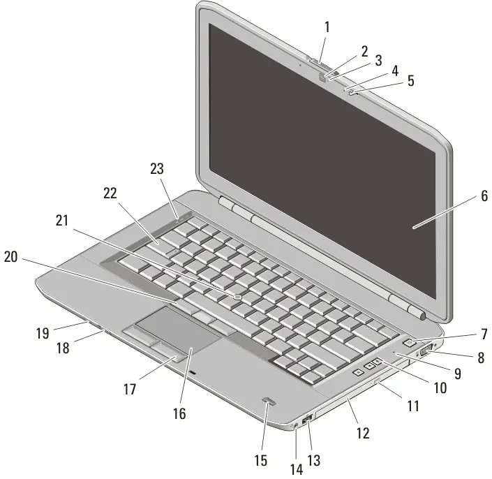
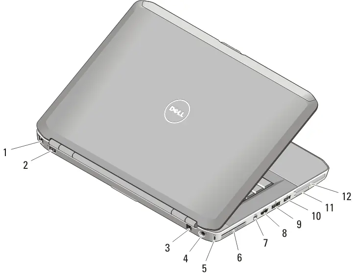
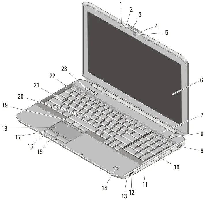
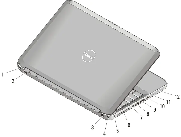
The manual provides detailed diagrams for the front and back views of the Latitude 5420/E5420/E5420m and 5520/E5520/E5520m models. Key components identified include the display latch, camera, microphone, power button, various USB connectors, VGA, HDMI, IEEE 1394, and card slots.
Quick setup
Before starting, ensure you have read the safety information provided with your computer. Follow these steps for initial setup:
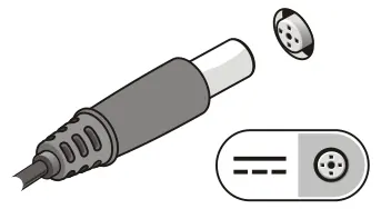

- Connect the AC adapter to the computer and an electrical outlet.
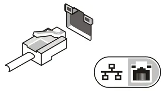
- Connect the network cable (optional).
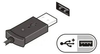
- Connect USB devices such as a mouse or keyboard (optional).
- Connect IEEE 1394 devices (optional).
- Open the display and press the power button to turn on the computer.
Note: It is recommended to turn the computer on and off at least once before installing any cards or connecting to a docking device.
Safety and maintenance
To prevent damage or fire, do not block air vents or store the computer in a low-airflow environment (e.g., a closed briefcase) while it is running. Fan noise is normal and indicates the system is cooling itself. When disconnecting the AC adapter, always grasp the connector, not the cable, to avoid damage.
Technical specifications
The manual lists detailed specifications including:
- Chipset: Intel HM65 or GM45 Express chipsets depending on the model.
- Processor: Intel Core i3, i5, i7 series or Intel Core 2/Celeron series.
- Memory: Two DIMM slots supporting DDR3 SDRAM (1066MHz or 1333MHz), capacity from 1GB to 8GB. Note that only 64-bit operating systems support more than 4GB of memory.
- Battery: 4-, 6-, or 9-cell smart Lithium-ion batteries.
- Environmental: Operating temperature 0°C to 35°C, humidity 10% to 90% (non-condensing).
Manufacturer information
Dell Inc.
Practical help
Common problems
Computer overheating or fan noise
Ensure air vents are not blocked and the computer is not stored in a low-airflow environment like a closed briefcase while running.
AC adapter cable damage
Always grasp the connector, not the cable, when disconnecting. Ensure the cable follows the angle of the connector when wrapped.
Memory limit issues
Only 64-bit operating systems support more than 4GB of memory.
Before use
- Read the safety information shipped with the computer.
- Verify the AC adapter is compatible with your local electrical outlet.
- Ensure the computer is placed on a flat surface with clear airflow for vents.
- Perform an initial power-on and shutdown cycle before installing hardware.
Specs in practice
- AC Adapter Input
- 100 VAC to 240 VAC, 50 Hz to 60 Hz, compatible worldwide.
- Operating Temperature
- 0°C to 35°C (32°F to 95°F).
- Maximum Altitude
- Operating up to 3048 m (10,000 ft).
Images and diagrams
- Figures 1 and 3 identify front-facing components like the display latch, camera, and power button.
- Figures 2 and 4 identify rear-facing ports including network, USB, HDMI, and e-SATA connectors.
- Figures 5-8 illustrate the physical connection of the AC adapter, network cable, USB devices, and 1394 devices.
Model compatibility
- Offerings and specifications may vary by region.
- Some devices mentioned may not be included depending on your specific order.

Manual page author
David Miller
Documentation analyst
Organizes user manual content into clear summaries, with attention to model details, product context, and everyday usability.