Home / Door Hardware
Installation Manual for Detex 03CM Mortise Trim
Quick installation guide for the Detex 03CM Mortise Trim. Includes tools required, door preparation steps, hole drilling specifications, and trim installation procedures.
Table of contents
Manual images
Click an image to enlargeQuick Installation Guide
The Detex 03CM Mortise Trim is designed for use with exit devices. The recommended height from the finished floor to the trim/device centerline is 40 inches. Always wear safety glasses before beginning the installation. Ensure you have the correct plastic template for your door handing (LHR/RHR) to mark the holes accurately.
Tools and Supplies
- Safety Glasses
- Pencil
- Center Punch
- Hammer
- Drill Motor
- Drill Bits & Taps
- Screw Driver (Phillips Drive)
- Tape Measure
Step 1: Door Preparation
Use the provided plastic template to mark the trim holes. If you are unsure of the trim/device centerline location, measure the pocket to determine the lock centerline.
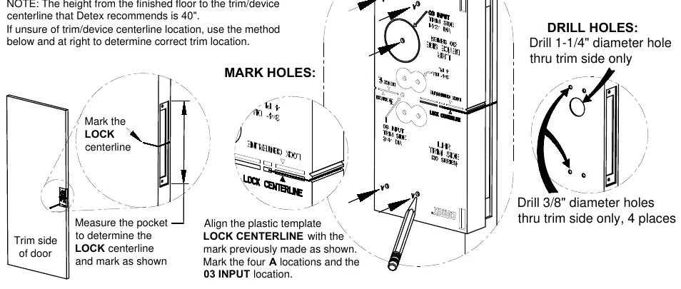
- Mark the lock centerline on the door.
- Align the plastic template lock centerline with the mark on the door.
- Mark the four mounting hole locations (A) and the 03 input location.
- Drill a 1-1/4 inch diameter hole through the trim side only for the input.
- Drill 3/8 inch diameter holes through the trim side only at the four marked locations.
Step 2: Trim Installation
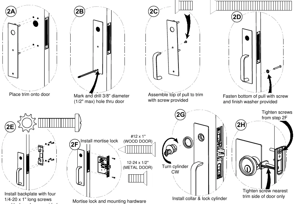
- Place the trim onto the door.
- Assemble the top of the pull to the trim using the provided screw.
- Fasten the bottom of the pull to the trim using the provided screw and finish washer.
- Install the backplate with four 1/4-20 x 1 inch long screws and lockwashers (provided with the exit device).
- Install the mortise lock and mounting hardware provided with the exit device, fastening screws loosely.
- Install the collar and lock cylinder. Turn the cylinder clockwise (CW) to secure.
- Tighten the screw nearest the trim side of the door only.
- Tighten all remaining screws from the previous steps.
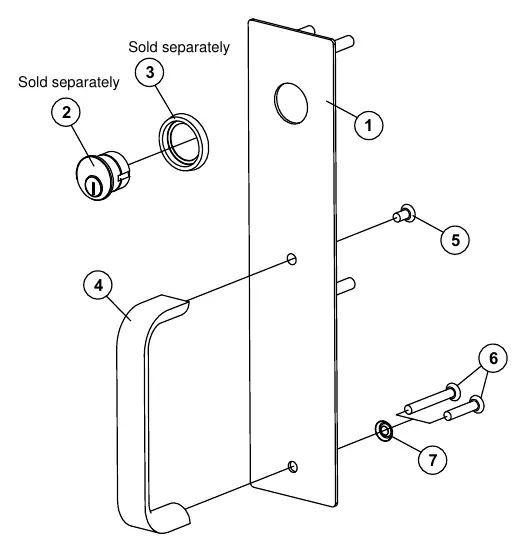
Parts Breakdown
The assembly consists of the trim plate (03WM), mortise cylinder (5 pin), cylinder collar, pull (03C), and various machine screws (1/4-20) and washers. Ensure all parts listed in the breakdown are present before starting installation.
Manufacturer information
Detex Corporation
Practical help
Common problems
Trim does not align with the door pocket
Verify the lock centerline measurement and ensure the plastic template is aligned correctly with the mark on the door.
Cylinder is loose
Ensure the cylinder is turned fully clockwise (CW) to secure it properly.
Before use
- Wear safety glasses.
- Measure 40 inches from the finished floor for the trim/device centerline.
- Verify you have the correct template for LHR/RHR doors.
- Ensure you have a drill, center punch, and screwdriver.
- Check that all parts (trim plate, pull, screws) are present.
Specs in practice
- 1-1/4 inch hole
- Main input hole required through the trim side of the door.
- 3/8 inch hole
- Mounting holes required at 4 locations.
Images and diagrams
- Exploded view shows parts 1-7 including trim plate, pull, and screws.
- Installation steps show drilling locations and assembly sequence.
Model compatibility
- Designed for use with Detex exit devices.
- Compatible with both wood and metal doors (different screws required).

Manual page author
Michael Turner
Technical manual editor
Reviews PDF manuals for structure, safety notes, and practical product details so readers can find the right information quickly.